For TomoTherapy
Patient
Quality Control With Dosimetry Check
Version 6
September
2018
Math
Resolutions, LLC
5975 Gales
Lane
Columbia, MD
USA 21045
Dosimetry
Check is owned by Lifeline Software
Note: Second Check with Dosimetry Check is
not cleared in the US by the FDA
nor is there CE Mark by the European union.
Two
dimensional source model for second check
Treatment
Plan Download for Second Check
Geometry File
for Second Check
Introduction
This supplement adds material in regard to the second check capability of Dosimetry Check for the TomoTherapy machine. Please refer to the TomoTherapy supplement for other details of the support of the TomoTherapy machine by Dosimetry Check. Second check refers to recomputing the dose to the patient and displaying the results based only on the down loaded treatment plan. In addition, the Dosimetry Check tools are available to compare the dose computed by Dosimetry Check to the treatment plan dose.
Second check computes the dose from the treatment plan only. A two dimensional source model is used to compute the fluence distribution considering the position of the leafs and jaws.
Warning: Second Check Only Checks the Plan,
Not the Delivery
Two dimensional source model for second check
There are two source models in Dosimetry Check for the TomoTherapy machine. The one dimensional longitudinal source model is used for dose computation using the detectors for modeling TomoEdge in the direction of the Y IEC axis (patient head to feet), as the detectors only measure the dose on the X axis of the treatment beam. A more general two dimensional model was required for second check to compute the intensity after passing through the modeled leafs.
The model is fitted using the same measured profile along the IEC Y axis used for the longitudinal model. However, the jaws (and leafs) are represented in their respective planes with a two dimensional contour. An exponential is used to describe the source intensity at radius r in the source plane from the central axis. The intensity is summed up by considering the path rays take through the jaws and leafs. Program FitTomoSourceModel or GenerateBeamParameters fits this model as well.
Treatment Plan Download for Second Check
You must run the version 3 release 8 or later of program ReadDicomCheck for Second Check as the leaf positions are not be saved in the prior versions.
Theory of Operation
The position of the jaws and leafs for each control point read from the Dicom plan file exported from the TomoTherapy planning system are used to compute a two dimensional fluence intensity map between two control points. A stationary beam is then modeled from this intensity map at the gantry angle and couch location (position of isocenter within the patient), the average of coordinates between the two control points, and used to compute the dose to the patient with an external beam dose algorithm. The dose to the patient is computed from the sum of all such beams. If there are N control points, there will be N-1 beams. The continuous movement of the couch and gantry is approximated by the N-1 fixed beams.
Geometry File for Second Check
For Second Check there is an additional geometry file to describe the jaw and leaf geometry in more detail. However, this file is optional since it is unlikely that the parameters will be different for different machines. The values will default if this files does not exist. The file name is TomoGeometry.txt and an example is shown below:
/*
file format version */ 1
/* This file holds geometry information about the jaw and
leaf geometry of
the TomoTherapy machine. Currently the
file Geometry holds
more basic geometry and the geometry
about the
detectors.
If this file does not exist, default values
are used.
*/
/*
jaw_top distance cm */ 9.0
/*
jaw_bottom distance cm */ 22.5
/*
leaf_center_spacing degrees*/
0.413766
/*
leaf_width degrees */ 0.413750
/*
leaf_top distance cm */ 22.876
/*
leaf_bottom distance cm */ 32.8707
/*
bottom_length distance cm */ 1.84
/* groove_length cm
*/ 4.918
/*
tong_groove_depth cm */ 0.0305
/*
tongue_side on -x side -1, */
/*
on +x side 1 */ 1
/*
machine sad cm
*/ 85.0 // redundant with
Geometry file
/*
attenuation fraction through the leafs */ 0.003
/*
future paramenter: */ 0
Second check calibration
The monitor unit must be calibrated. The user is advised to calibrate to a measured dose, but can choose to calibrate to the planning system. In any event, one must first do a plan. Then run program SetTomoSecondCheckDose.exe from a command prompt window. Select the machine, the nominal jaw width, and the algorithm between pencil beam and collapsed cone. Then enter the desired dose (measured or from the planning system), and then enter the dose that was computed by Dosimetry Check. The program will scale the compute constant so that the entered dose will be computed, and the computed constant will be stored in the files TomoSecondCheckConstant with the ending for the algorithm and width, as shown for CC and 25 mm: TomoSecondCheckConstantCC25_06. This program must be run for each width and algorithm, for a total of six possible combinations.
Running Dosimetry Check
After downloading the plan for second check, no further action is needed before running Dosimetry Check. Dosimetry Check does require an external outline to define the patient, and this can be done in ReadDicomCheck or Dosimetry Check.
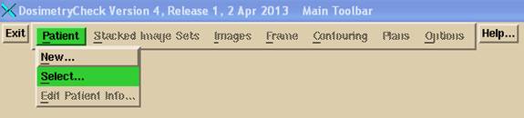
Select the patient:
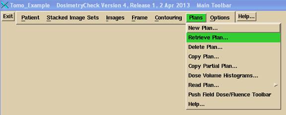
then select the plan:
On the calculate pull down select the algorithm:
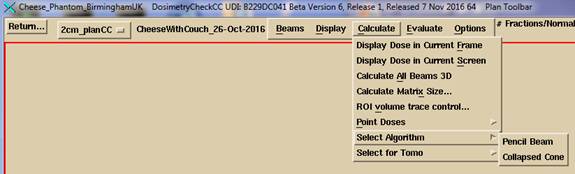
On the Calculate pull down on the Plan Toolbar, select whether to compute with the detector or do second check:

Refer to the TomoTherapy supplement manual for computing the dose based on measurement of the radiation field with the detectors (a detector record file must be selected).
For second check, just select second check.
Compute the dose:
For TomoTherapy, there is no compute on demand (computing only the points required for a particular purpose). The entire patient volume is computed at once when a computed dose is called for. This is because there can be up to thousands of beams, depending upon the number of control points, and the dose matrices of those individual beams, if saved, would exhaust the memory address space.
Refer to the Dosimetry Check reference manual for further details on Dosimetry Check, the TomoTherapy supplemental manual, and the System2100 reference manual.