Collimator rotation and measured fluence
Collimator Rotated So Field Fits on EPID
Beam Toolbar
|
Beam Toolbar |
Upon creating or selecting a beam from the plan toolbar, the beam toolbar is displayed. The user must first pick the treatment machine with the provided option menu. Thereafter the treatment machine may not be changed. On the toolbar the plan name is shown to the right of the return button. An option menu is next shown for the beam. A different beam may be selected with this option menu among beams in the plan. An option menu follows showing the treatment machine, but other choices are grayed out once a machine is selected. Next is an active toggle button. The beam may be selected to be inactive (out), in which case the beam is not displayed or computed. The energy is next selected with an option menu. Be careful to select the energy desired for dual energy treatment machines.
Move
Under the Move pull down are controls to set the isocenter position, the couch, gantry, and collimator angles, and depth of isocenter or source to surface distance.
Move Isocenter
|
Move Isocenter Popup Control |
The move isocenter popup provides control for setting the isocenter in terms of couch coordinates. Couch lateral corresponds to the IEC accelerator X axis. Couch longitudinal corresponds to the Y axis and couch height to the Z. Each control has a coarse wheel that changes the coordinate in increments of 1 cm, a fine wheel that changes in increments of 0.1 cm, and a text field where the coordinate can be typed but must be completed by hitting the Enter key. The wheels have areas at each end where they may be moved in single increments with a mouse click, and a home button that resets to zero or the default value for that coordinate.
While the coordinates are changed, the beam will be drawn in frames that are displaying the plan.
A pulldown menu is provided to set the isocenter at the location of another beam in the same plan.
Move Angles
|
Move Angles Popup Control |
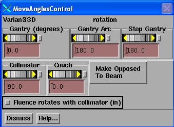
The gantry, collimator, and couch angles may be set here. Also, an arc may be set by setting the Gantry Arc control to a non-zero value. However, for IMAT, the arc setting is ignored here as the arc will be simulated with fixed beams with images captured during the rotation.
A pull down menu is provided to set the current beam parallel opposed to an existing beam (including itself) in the same plan.
Collimator rotation and measured fluence
For example, if the collimator angle is 45 degrees for treatment, then because the EPID does not rotate with the collimator, the 45 degree rotation is already accounted for in the EPID image because the EPID does not rotate with the collimator, rather you can see the field rotated in the EPID image. When the EPID image is projected back onto the patient, the field will be in the correct rotated position. This is different from the situation where the imaging device rotates with the collimator. In that case, the image will have to be rotated with the collimator in the program for the field to be projected correctly onto the patient as it will appear in the image as unrotated.
Collimator Rotated So Field Fits on EPID
In this situation, rotate the collimator in the direction for which the field will now fit on the EPID. This can only be done for pre-treatment assessment when there is not a patient in the beam, not for exit-transit dose. Note the amount of rotation and in which direction. Did the collimator angle get larger or smaller? Let us say for an example that you had to rotate the collimator from the planned collimator angle of +30 degrees to +90 degrees. The rotation was then an extra +60 degrees. Then in Dosimetry Check, from the Plan toolbar, select under the Beams pull down to edit the beam. Under Move select Angles. Select “Fluence Rotates with Collimator” on (in). If the collimator had been left at 30 degrees in this example during the dry run, you would want to change the angle to 0, as noted above setting the angle to zero is equivalent to setting that the EPID rotated with the collimator (since the field will be projected with the 30 degree rotation in the image). Then to account for the extra collimator rotation during the dry run, rotate the collimator in the opposite direction 60 degrees from zero to the angle of -60 degrees. You have now compensated for the extra rotation. The field should be projecting in the correct orientation. Note that the beam’s eye view axes are drawn on top of the EPID image.
Set Depth and SSD
A control is provided to set the depth of isocenter or the source surface distance (SSD) of the beam. When specifying the depth or SSD, isocenter will slide along the present central ray to meet the depth or SSD specification. In order for this to happen the central ray must intersect the body skin boundary volume. If the central axis ray does not intersect the body outline, the depth and SSD text fields will be blank. When this control is up, the SSD and depth will be reported as the beam is otherwise moved.
Set Depth and SSD Popup Control
|
|
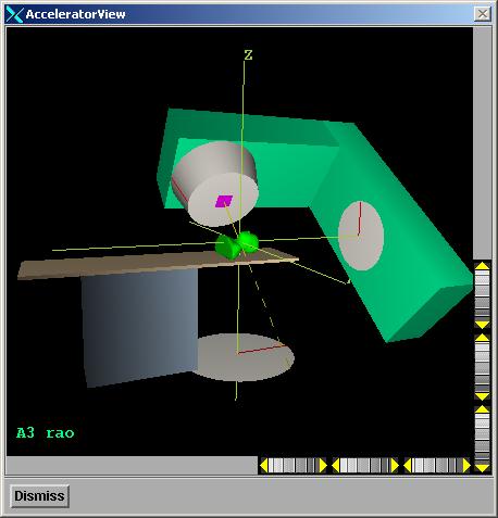
Visual Aid
|
The visual aid will show the accelerator in its current rotated state and serves as an aid in understanding the geometry of a particular beam. The skin boundary is displayed on the couch top. The name of the beam is in the lower left hand corner.
|
Options
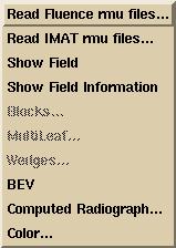 Options
for the Dosimetry Check program include to select the measured field to be
associated with the beam. Also, the
color used to draw the beam can be changed.
The color is used when the beam’s toolbar is not displayed. For moving the beam the overlay color used
for all drawing is used (if 24 plane graphics, XOR operation is used). BEV and computed radiographs are also
available.
Options
for the Dosimetry Check program include to select the measured field to be
associated with the beam. Also, the
color used to draw the beam can be changed.
The color is used when the beam’s toolbar is not displayed. For moving the beam the overlay color used
for all drawing is used (if 24 plane graphics, XOR operation is used). BEV and computed radiographs are also
available.
Read Fluence rmu files
Upon retrieving a plan, a plan function will run to search for rmu files for beams not associated with a measured fluence. The program looks in the directory with the path:
FluenceFiles.d -> plan_name -> beam_name -> IMRT
for files for the beam. In manual selection you will be able to navigate to any sub folder of FluenceFiles.d.
If files could not be found or you need to change the measured fluence used, you can reselect the files here. Note below that you can also read in more than one rmu file to add.
The current choices are to read an rmu (fluence or field dose array) file written by the Field Dose function or other functions that result in a field dose file, such as utilities that read EPID integrated image files or other electronic devices such as the PTW 729 ion chamber array or the MapCheck diode array. Here images have been located in beam’s eye view coordinates and converted to relative monitor units using a calibration curve or constant. An exception is made for images from an EPID that does not rotate with the collimator angle. For those devices, the program will set the collimator angle back to zero upon reading of the Field Dose file here, since the data is in the un-rotated position.
You may select more than one rmu (field dose) file for a beam. Doing so will result in the files being added together. This option is provided for the case as when a carriage shift might be required with the Varian MLC and each shift is integrated separately. The fluence files to add must all have the same pixel size, distance, and image size.
The program will create a screen of empty frames to display the fluence images for all the beams. On the file selection popup, select the fluences files for the current beam. If you hit the apply button, the field fluence image will be displayed, then the beam toolbar will be set to the next beam. Continue to hit the apply button after selecting the fluence rmu files for each beam, but be sure to check that you are selecting the correct files for the currently selected beam as shown on the beam’s toolbar option menu. Hitting the OK button instead of the apply will end the selection process after the current selection.
Read IMAT rmu files
For an IMAT beam, you will select all the rmu files that simulate the rotation of the beam. The files for each beam will be in a sub-directory of FluenceFiles.d with the path:
FluenceFiles.d -> plan_name -> beam_name -> IMAT
When you get the file selection box, select the correct directory (folder) on the left side of the file selection dialog popup. When you see the files on the right side, select all the files. Each rmu file has the gantry angle at which it was measured. The dose will be computed for a beam at each angle using the rmu file at that angle, the rotation simulated by the sum of all the beams at the different gantry angles. The gantry angle will be displayed in the image of each rmu file. A separate screen is created for each beam to hold the images for that beam.
Select Imat Images Spacing
This option will let you combine images that are closer together in gantry angle than a minimum spanning angle selected here (see control below). The rotation is simulated by stationary beams, each one at the gantry angle of the rmu file. However, more beams will take more computational time.
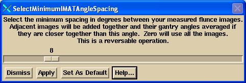
For example, if your images are every 5 degrees and you select 10 degrees, then images at 0 and 5 will add, 10 and 15 will add, 20 and 25 will add, etc..The angles will averaged so that the first angle will be reported as 2.5 from the 0 and 5 images, 12.5 for 10 and 15, etc.. In doing so, you reduce the number of beams used to simiulate a rotation which will save you computer time. However, you can expect some lose in accuracy, the lost greater the further you are from the center of rotation.
If you exit the program and reselect this patient and plan at a later time, your choices will be remembered. Likewise any change in the area restricted to will be remembered for the added and unadded images.
This operation is reverseable. If you select zero, all the original images will be displayed and used.
You can also set a default for all future plans. But changing the default will not effect other present beams in this plan. You will have to edit each beam as you have done this one.
If two or more images are added together, the image of the first image will be replaced with the added image, and the other images will not be shown. The gantry angle shown will be the gantry angle used for the position of the image in all cases.
If you want to compare results, the suggestion is that you copy the plan, and then compare the two plans, making changes to one of the copies. Copy plan is found under the Plans toolbar. You can only copy a plan that has been selected and is currently read in.
This utility does not save the dose matrix computed from an rmu fluence array when you combine fields or restore when using the orginal images.
Show Field
There is also an option to redisplay this field dose image again by first selecting an empty frame and then selecting the Show Field function under the Options menu pulldown.
Show Field Information
Selecting this option will display information about the field fluence as to what files were read and the calibration and deconvolution parameters.
New Fluence Images
If new fluence images are generated, then upon retrieving a plan, the new files will be detected but not used unless the user chooses to replace the old fluence with the new.
Computed Radiograph and BEV
A computed radiograph and BEV may be selected to be displayed. A BEV is a solid model 3D perspective with
the eye at the source of x-rays. A
computed radiograph may be in the background or may appear by itself. If the beam is moved, the computed
radiograph will be erased.
The computed radiograph is selected under the Options pull down.
|
DRR Toolbar |
Select an empty frame (by clicking the mouse on the large button
occupying an empty frame). You can
create a screen of empty frames with the Screen Control button (lower right and
side of the main program window).
The contrast enhancement slider will raise CT numbers to the power
selected to simulate photoelectric effect.
Four is a good choice. You can
add the computed radiograph (or DRR for Digitally Reconstructed Radiograph) to
an existing BEV for the beam, or create a new BEV with the computed radiograph
as background, or you can show the DRR by itself.
|
Example DRR for an
oblique field. |
An example DRR is shown below, with corresponding outlined regions of
interest.
The Frame
Control at the bottom of the 3D frame may be used to control objects being
drawn.
Modulation
Hitting this button will
modulate the DRR with the fluence image for the beam. In doing so the DRR will be a representation
of a port film. Putting a transparent
ROI on top of this will give an indication of where the beam is relative to the
body anatomy.
Utilities
A utility exist to dump a 3D dose matrix for the beam to a file. This binary file will have the dose matrix in beam’s eye view coordinates, in the units of centiGray. The file is used by program AnalyzeBeam to compare computed dose to that measured with scanning equipment. Computed and measured beam profiles may then be plotted together for comparison purposes. This option is generally used for quality control purposes.
Machine Geometry File
The geometry of the treatment machine is specified in the Geometry file in the subdirectory of the treatment machine. All machines are stored in the directory specified by the BeamData.loc file in the program resources directory. Each machine occupies a subdirectory under that directory and contains a Geometry file.
The Geometry file contains information about the treatment
machine. An example file is shown in the
section on BeamData. Of importance here
is the definition of directions and coordinates for the treatment machine
parameters. For example, the gantry
angle at which the machine points at the floor and the direction of rotation
that represents an increase in that angle.
This file should be edited to fit your machine. The beam coordinates are stored in IEC
coordinates and the Geometry file is used to translate those coordinates to the
user interface. Changing the
definitions of the accelerator’s coordinates system will not change the
location of existing beams.