Existing patient or plan, or a new
plan
CT number to Density Conversion
ReadDicomCheck
Run
the program ReadDicomCheck to import plans in Dicom RT format to Dosimetry
Check. You can select this program from DosimetryCheckTasks,
or you can run the program from the current directory by typing:
ReadDicomCheck
in
a command prompt window.
Below
is a picture of the main window for this program:
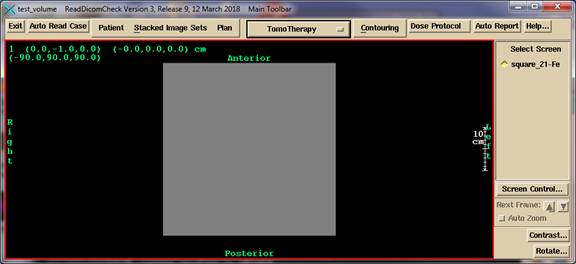
This
program will read in Dicom RT files and write out the patient directory with
the plan for Dosimetry Check to pick up.
The planning system should write out the plan into Dicom RT files, which
are then read. Either navigate
to the directory where these files are, or copy them into some convenient
directory. By default, the file
selection box starts in the directory where it expects to find image files as
defined in the file NewDicomRTDirectory.loc in the program resources directory,
or if that file is not present, then the file NewImagesDirectory.loc. The CT scans will be each in a separate
file. The outlined region of interest
structures, plan, and 3D dose matrix are assumed to be in different files. These files may or may not start with
convenient prefixes, such as the structure file starting with the letters RS,
the beam geometry in a file starting with the letters RP, and the 3D dose
matrix in a file starting with the letters RD.
After reading in the Dicom RT files, run Dosimetry Check and select the
patient directory created here, and then the plan created here. Below are comments on running the program
ReadDicomCheck.
Coordinate Systems
The
Dicom standard is that the coordinate system is to be Dicom, and everything, CT
images, isocenter, points, region of interest contours, must be in the same
coordinate system (otherwise how would one know where isocenter is relative to
the CT scans, etc.). Further, the Dicom standard states that the medical
accelerator coordinates (referring to gantry angle, couch angle, collimator
angle, etc.) must be in IEC coordinates.
Internally Dosimetry Check is IEC, so no transformations are needed upon
reading in accelerator coordinates. The
Geometry file (see beam data section) is only referred to in presenting a
machine coordinate to the user (see Beam below).
Therefore,
after passing through the Dicom filter,
all information
about the coordinate system used in the treatment planning system is lost and
unrecoverable.
The
coordinate system used by Dosimetry Check is IEC, not Dicom. IEC is positive Y axis toward the patient's
head, positive Z axis posterior to anterior. Only the X axis agrees with Dicom. The origin is at the center of the box that
holds all the CT scans, hence is dead center in the
patient model.
Patient
You
have to first create a patient or select an existing patient in your present
system unless you are going to use the Auto Read Case option below.
Warning
Selecting Patient:
Once you have selected a patient, the program will continue to use
the same patient. You have to back out
of the program to select or create a different patient. Be sure you are putting files into the
correct patient directory.
The
current patient’s name is shown on the title bar of the main application
window.
If you don't know the patient's name you can
get it from any CT scan file using program DicomDump in the tools.dir directory
respectively. This program is an ASCII
program. Invoke with the program name
followed by the name of the CT scan file to read. You might want to pipe to the more function,
for example:
DicomDump file_name | more
You can also access the program from DosimetryCheckTasks
or MarkRT tasks, in which case you will get a file selection box where you can
navigate to the file and select it.
Look
for Dicom (10,10).
Other
Dicom display functions can be found on the internet.
Create
the patient if a new patient or select an existing patient. It is your responsibility to guarantee that the
images and plan belong to the correct patient, and that the plan is for the
stacked image set selected.
Auto Read Case
You
may use this feature to read in a case. You
do not have to first create or select a patient. The program will do so from the patient’s
name in the Dicom plan file. But you
must back out of the program to create or use a different patient. By selecting a patient, you can over ride
which patient where the data goes.
You
must navigate to the top of a directory tree that will contain all the files
for the case: CT scans, structure file,
plan file, and dose file. There can be
more than one patient and case in the directory tree. The program will present you the list of
patient-plans that it finds, and you are to pick one. Selecting this option the program will do the
rest but you should review the messages when it finishes. You might have to
select the accelerator for instance if the machine name in the plan is not in
the list of machines for Dosimetry Check or MarkRT.
This
auto feature will also accept MRI scans.
But
this function has the limitation that you can only use it once, there after you
will have to back out of the program (hit Exit) and then select to run the
program again. The limitation is that only one stacked image set can be
supported per run. However, you can
manually select a second plan (and then dose) to read in for the same stacked
image set and patient (see below)
If
you have a second plan for the same stacked image set, then select the stacked
image set and manually select the plan and dose file below. If you use the Auto Read Case feature, you
will end up with a duplicate stacked image set.
However, if your contours for the second plan are different, you might
want a duplicate stacked image set for the plan. Each plan is associated with a
stacked image set, but a stacked image set can be used by more than one
plan. ROI contours belong to the stacked
image set in Dosimetry Check and MarkRT, not the plan.
Manual
entry
If
these conditions are not met, you can select individual components as described
below.
Existing
patient or plan, or a new plan
For
an existing patient, select the patient, and then select the stacked image set
if the plan is for the same image set.
For an existing plan you can reselect the same plan file and over write
the existing plan. For a new plan, just
select the new plan file. In Dosimetry
Check you will be able to select which plan you want to view, and you can view
multiple plans in the same run of Dosimetry Check. You just have to be aware of which plan you
are showing in a particular frame and which plan’s tool bar you are working on.
Stacked Image Set
You
next have to select an existing stacked image set or read in a new one. The plan to be read has to be for the stacked
image set. If creating a new stacked
image set, use the filter on the file selection box to read in only scan files,
for example, by setting the filter to CT*.
Then select all files to read in.
This program will here allow you to only select or read in one stacked
image set. Back out of the program if
you have to read in a second one. This
stacked image set is the primary image set for the plan which supplies the
external body outline and the CT number to density conversion function.
CT number to Density Conversion
There
is no mechanism in Dicom RT for specifying how CT numbers are converted to
density. Therefore you will still have
to provide a conversion for Dosimetry Check.
Go under StackedImageSet to Options to Density. You can read in a scan of a phantom with
biological materials (by creating a stacked image set out of the scan) and run
a curve. You can also type in numbers if
you have values. Water density for most CT scanners have a pixel value of 1024 in Dosimetry
Check. Dosimetry Check does not use
Hounsfield numbers. A Houndsfield number
of -1000 would be a pixel value of 24, 0 1024, and 1000 2024.
Regions of Interest (ROI)
Once
you have read in the stacked image set you should read in outlined regions of
interest (ROI). There is a mechanism for
identifying which ROI is the external body outline. However, if that fails or is absent, you will
have to select the body outline or create it in Dosimetry Check. To create a body outline, use the tool for
that purpose under Contouring. To select
an existing body outline, go under StackedImageSets to Options to Skin. You might want to check the choice as a
matter of routine. There is a check to
see if the ROI came from the selected stacked image set.
Generally
the Dicom RT ROI file starts with the letters RS.
Options
You
can push the Stacked Image Set options toolbar to make selections for the CT
number to density curve, and the ROI volume that is to be the body contour.
Plan
Once
you have the stacked image set, you can read in a plan. Here we only pick up the beam positions
(gantry, collimator, and couch angles, and isocenter location) and 3D dose
matrix. First select to read in the
beams by reading in the plan file. You
must read in the beams first and then select to read in the dose matrix
second. You cannot read in the dose
matrix without having read the beam file first in the same session. This is because there is information about
the plan in the beam file that is needed by the dose matrix function that is
not provided in the dose file. There is
a check that the dose file is for the selected beam file.
Generally
the Dicom RT beam file starts with the letters RP and the dose file with the
letters RD.
Beams
If
the accelerator machine name is not one that exist in
the treatment machine directory, you will be prompt to select the accelerator
that the beams are to use. This choice
will apply to all the beams. Naturally
the selected machine must have the required energy. Dicom RT specifies the accelerator
coordinates in IEC coordinates, which is also the system for Dosimetry Check,
so no conversion is needed here. The
Geometry file in each machine directory simply specifies how the coordinates
are presented to the user. For example,
for a non-IEC accelerator, the gantry angle will be converted from IEC to the
system specified in the Geometry file when presented to the user. Changing the Geometry file will therefore not
change the actual angle of a beam, only the angle reported to the user. This will not apply of course if the user
types in an angle.
If
the machine name in the plan read above is not found in the list of machines in
Dosimetry Check, then you will be prompted to select an accelerator. You will always have the option of picking a
different machine afterwards. The
machine list in Dosimetry Check is the list of directory names in bd.d. The option menu will show the accelerator that
was picked.
Contouring
You
can push the contouring toolbar to complete any needed contouring, assignments
of densities to region of interest volumes, and creation of a couch model.
Dose
Protocol
Use
this button to select a protocol file for the dose limits for ROI volumes. If the protocol is being read from the Dicom
structures and plan file, then you will not need to use this function. This function was added for version 3 release 9 for ReadDicomCheck and is supported in
DosimetryCheck version 5 release 7 (and later in all cases).
If
you are not using Dicom from your planning system, and if the plan name matches
the name of a protocol file you have written and is in the folder
data.d\VolumeDoseLimitProtocols.d
then
that protocol file will have been copied in already. The file written from
numbers found in the Dicom download are written to the file DoseReferenceVolumes.txt
in the plan folder. If copied from the
protocol folder, the name of the file will be VolumeDoseLimits.txt.
You
should select the button before reviewing the auto report as volumes listed in
the protocol file will be added to the list of volume to compute dose volume
histograms.
Note
that this program and DosimetryCheck will strip out characters not legal in a
file name for the plan name and the name of ROI volumes, and will replace a
space with an underscore. This must be
taken into consideration when writing and naming your protocol files.
Auto
Report
For
automatic processing of EPID images to occur you must make selections for the
auto report, input the dose for gamma analysis and the gamma criteria. If this section is incomplete the auto report
cannot be produced automatically.
Saving of Dicom Files
All
the imported files are saved under the sub-directory Imports.d in the patient’s
directory.
Dosimetry Check
After
reading in the plan, exit the program and run Dosimetry Check (or MarkRT). Select the patient, stacked image set, and
then the plan. For each beam you must
read in a fluence file (in rmu units).
Dosimetry Check shows the dose in the resolution selected under
Evaluate. For example, if Dosimetry
Check has the default value of 0.5 cm, then a matrix of that spacing is
provided for any selected plane. Doses
are interpolated out of the 3D dose matrix read above. If the imported 3D dose matrix has a spacing
of 0.1 cm and the above is set to 0.5 cm, you will see the isodose curves
plotted on a 0.5 cm matrix. There is an
option under Evaluate on the Plan toolbar to show just the dose from the
treatment planning system. Dosimetry
Check could thus be used as a tool to display plans from other systems.