Using the Elekta iViewGT Imaging System
31 May 2017
Elekta
iViewGT Electronic Portal Imaging Device
Select the iViewGT Image System
Starting and stopping a time gantry angle file
Program ConvertEPIDImages and ConvertIMATImages
Elekta iViewGT Electronic Portal Imaging Device
Version 3.1 of Elekta’s (Elekta,
When the iViewGT system is put into integration mode, one must select the option of having each segment written out as a single file. As of this writing, an available composite mode does not correctly add up the individual segments, although a final image is available. We have also noted that one might have to interrupt the accelerator between segments to give the iViewGT system time to write out the segment files.
We are providing a utility program here: IviewToDicom to be used in the general case. This utility will read the iViewGT data base and assemble all the segment files for each beam.
IMRT
This utility will then write each IMRT beam out in a single Dicom file coded so that program ConvertEPIDImages can read the files. The manual for ConvertEPIDImages is then to be referred to. Each segment is also written out in a subdirectory for reference only.
VMAT
For VMAT each segment is written out as a separate Dicom file. Program ConvertIMATImages is then to be referred to import the images. The composte image is written out for reference only.
Program IviewToDicom
This utility program will read the iViewGT data base and assemble the segment files for each beam, adding up the segments while applying the scaling factors and putting out both the composite image and images for each segment. The Dicom files are then written out in Dicom format to the new EPID images directory, in sub-directories by the patient name then by the plan name, then by the beam name for the individual segments. See the location file NewEPIDImagesDirectory.loc in the program resources directory for defining where the image files are written to. An example file is
/* File
format version: */ 1
//
directory where new images will be deposited:
<*h:/images.d*>
Note the slash in a path can be either / or \. The program will convert to what ever system the software is on (Windows or Linux). The program resources directory is in turn defined by the file rlresources.dir.loc in the home directory. Read the ASCII file standard in the Program Resource Files section of the System2100 manual.
The files are coded so that utility program ConvertEPIDImages and ConvertIMATImages can read them. IviewToDicom is licensed separately.
IViewGTDirectory.loc
A text file is read in the program resources directory that contains necessary information of where to find the iViewGT data base. A sample files are shown below. The file format for version 2 release 3 of IviewToDicom is shown below.
/* file
format version */ 3
/*
number of systems to follow */ 2
/* for each system: */
// description of system.
<*Elekta IViewGT on 1*>
//
path to the iViewGT directory where PATIENT.DBF is:
<*g:\iview\db*>
//
translation of L, M, H, energy designations:
L 6
M 10 H 15
//
directory for calibration images.
<*c:/Elekta1/Calibration.d*>
//
directory for pre-treatment images
<*c:/Elekta1/PreTreatment.d*>
//
directory for exit images
<*c:/elekta1/Exit.d*>
//
location of where to look for the inclinometer file
<*c:/incline_files1.d*>
// description of system.
<*Elekta IViewGT on 2*>
//
path to the iViewGT directory where PATIENT.DBF is:
<*v:\iview\db*>
//
translation of L, M, H, energy designations:
L 6
M 10 H 18
//
directory for calibration images.
<*c:/Elekta2/Calibration.d*>
//
directory for pre-treatment images
<*c:/Elekta2/PreTreatment.d*>
//
directory for exit images
<*c:/elekta2/Exit.d*>
//
location of where to look for the inclinometer file
<*c:/incline_files2.d*>
The prior file format version 2 (for
version 2 release 1) does not have the inclinometer location entry. That entry specifies where the file
selection box starts at. The user can
always type in a new path in the filter text box.
The prior version 1 file format (prior to version 2 release 1) does not support automation:
/* file
format version */ 1
/* number
of systems to follow */ 2
/* for each system: */
// description of system.
<*Elekta IViewGT on 1*>
//
path to the iViewGT directory where PATIENT.DBF is:
<*g:\iview\db*>
//
translation of L, M, H, energy designations:
L
6
M
10
H
15
// description of system.
<*Elekta IViewGT on 2*>
//
path to the iViewGT directory where PATIENT.DBF is:
<*v:\iview\db*>
//
translation of L, M, H, energy designations:
L
6
M
10
H
18
For
each iViewGT system there must be an entry consisting of a description text
field, the path to the system from the computer IviewToDicom is running on, and
translations for the letter L, M, and H to energy in mV. /* to */ are comments not read as well as //
to the end of a line. Text fields are
set off with <* to *> if there are spaces in the text field. One would do an NFS mount which need only be
for reading, between the host computer and the iViewGT system computer. Keep the description of the system fairly
short as the description will appear on the below option menu on the main
toolbar of IviewToDicom shown next below.
Select the iViewGT
Image System
The
main toolbar is shown below:
![]()
Use
the first option from the left after the Exit button is an option menu to
select the IViewGT system if you have more than one from the list in the above
file.
Select
the Delivery Type
Next
there is also an option menu to select IMRT cases (more than one segment per
beam), Conventional cases (only one segment per beam), VMAT, and CFS mode. The iViewGT system marks those image files
differently (IMRT and CFS is of type ‘T’, conventional and VMAT is type
‘P’). However, a file for a beam name
with the letters “cal” in the name that is of type P will be read with the IMRT
and VMAT choice so that the conventional calibration file can also be included
in the list of found beams, except for the case of CFS. Do not make a calibration file of type T
(IMRT) and give it the same plan name as the plan delivered if CFS mode is to
be used. Read in the calibration file
separately under conventional. The
letters used by IviewGT are:
|
ASCII
value |
letter |
Image
type |
|
80 |
P |
port
image |
|
84 |
T |
integrated
IMRT image |
|
77 |
M |
multi
exposure |
|
68 |
D |
double
exposure |
|
83 |
S |
sim
image |
|
82 |
R |
DRR
image |
CFS
Mode
For
CFS mode, you will be prompted to select the patient from the Dosimetry Check
patient list when you select CFS mode. To
pick a different patient, select CFS again.
You must have first
read in the plan with program ReadDicomCheck.
This
progam will need the list of beams in the plan, the gantry angle for each beam,
and the number of segments for each beam, in order to sort out the integrated
images as iViewGT stores the delivery of all beams and segments under the name
of the first beam delivered. If a plan
with the same name from iViewGT cannot be found, you will be prompted to select
the plan from the list of plans under the selected patient’s name. If the first beam treated cannot be
determined, you will be prompted to select the first beam. However, in this last case, there may very
well be an error as the gantry angle of the first beam treated is known and
should be found from the beam list in the downloaded plan.
Select
IViewGT Patient
After
selecting the type of plan, select the patient from the iViewGT data base by
hitting the button “Select IViewGT Patient”.
The program will list the patients found on the iViewGT system and
prompt you to select one.
This is not to
be confused with selecting the patient entry in Dosimetry Check above for CFS
mode.
The
program will then find all files that were integrated for the patient. If more than one plan is found, you will be
prompted to select the plan. The
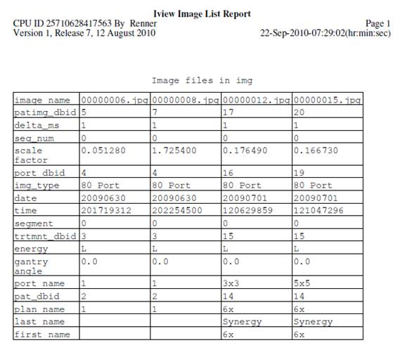
program will then list all the segment files found, sorted by beam. An example appears below:
Iview
File List Report
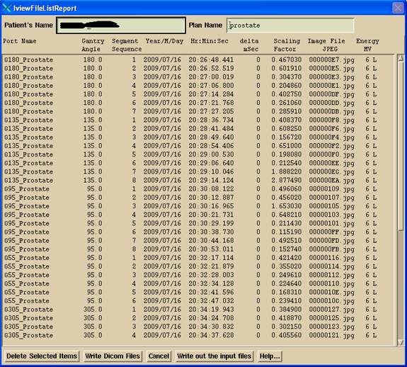
The
version after 25 Feb 2015 has additional choices at the bottom using version 2
of the loc file:
One
can remove from the list selected items.
The list is constrained to consider only then latest segments measured.
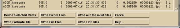
Write Out Dicom Files
Hitting
the “Write Dicom Files” button will write out a composite Dicom file for each
beam in the new images directory, and each segment will be written to a
sub-directory. The files will be written
to the directory defined by the loc file NewEPIDImagesDirectory.loc.
For
the loc version file 2 described about, there will be additional choices to Write Dicom Files to write to directories
being monitored for the automatic processing of EPID images. The user must pick which type of file is
being written out as they are going to different directories as defined in the
loc file. This is necessary for the
automated system to distinguish between a calibration image, pre-treatment
image, or exit image.
If
automation is not used, run program ConvertEPIDImges to read in these files
along with a calibration file and proceed, using a deconvolution kernel for the
iViewGT system. Run program
ConvertIMATImages for VMAT.
Inclinometer
For
IMAT (VMAT), there will be an additional popup requesting to locate the
inclinometer file for the images. The
inclinometer file will be written to the same folder that the Dicom image files
are written to. This is necessary for
the automation system to find the inclinometer file that goes with the image
files. Selecting the incliniometer file
with the image files with program ConvertIMATImages will also automatically use
the inclinometer file. See below for
more information.
Write out input files
The
“Write out the input files” button is for testing purposes and will copy the iViewGT
data base files read on the iViewGT system into the new images directory. For IMRT cases you will select the composite
images. For VMAT, you will select all
the segment images.
Dicom
File Output
The
program will export the Dicom RT files it creates to the folder named by the
NewEPIDImagesDirectory.loc as indicated above.
A sub-directory will be made out of the patient name, then the date of
one of the images (for versions on and after 15 Oct 2014), then a sub-directory
to that with the plan name. In that
directory will go a composite image for each beam. The composite image will be the sum of all segments
for a beam. If an IMRT case, it is the
composite image that you want to use.
For IMAT (VMAT) you use the individual segment files, one file for each
segment, NOT the composite image. In
this same directory, each beam will have a sub-directory that will hold the
Dicom files for the individual segments of a beam. And example is:
G135_Prostate.d G55_Prostate.d RI_G265_Prostate.dcm
G180_Prostate.d G95_Prostate.d RI_G305_Prostate.dcm
G225_Prostate.d RI_G135_Prostate.dcm RI_G55_Prostate.dcm
G265_Prostate.d RI_G180_Prostate.dcm RI_G95_Prostate.dcm
G305_Prostate.d RI_G225_Prostate.dcm
where
there is the Dicom RT image file RI_G265_Prostate.dcm
for beam G265 and the sub-directory G265_Prostate.d which will hold a Dicom RT
file for each segment of beam G265:
RI_G265_Prostate001_001.dcm RI_G265_Prostate006_006.dcm
RI_G265_Prostate002_002.dcm RI_G265_Prostate007_007.dcm
RI_G265_Prostate003_003.dcm RI_G265_Prostate008_008.dcm
RI_G265_Prostate004_004.dcm RI_G265_Prostate009_009.dcm
RI_G265_Prostate005_005.dcm RI_G265_Prostate010_010.dcm
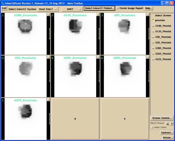
A screen will be made in IviewToDicom that
will hold a frame for each the composite image of each beam, as shown
below. The screen name will be the plan
name:
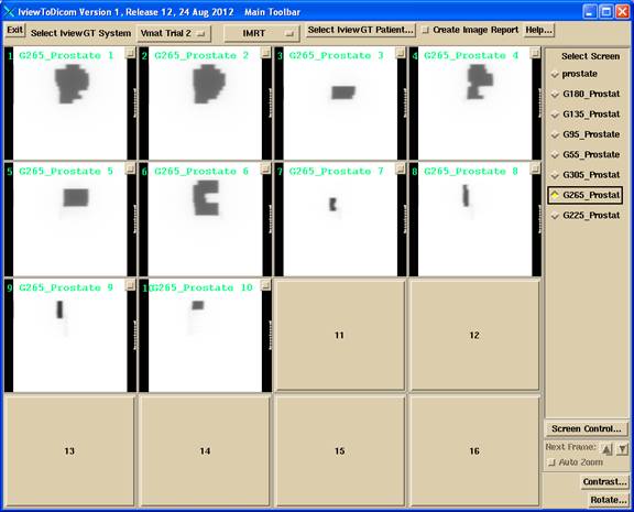
There
will be a separate screen for each beam that will hold the segment images for a
particular beam, such shown below. The
screen name will be the beam name.
Inclinometer
File for VMAT
For
images that belong to a VMAT case, the program will prompt you to select the
inclinometer file for the images as shown below:
Simply
select the corresponding file which starts with the letters IA that was made
when the images are integrated on the IviewGT system. The program will copy the file to the same
folder with the Dicom image files. When
selecting the inclinometer file with the image files (use “Select All”) in
ConvertIMATImages, the inclinometer file will be recognized and applied. The location file InclineDirectory.loc in the
program resources directory specifies the default location of where the inclinometer
files are written to (prior to 12 Dec 2014, use the file
NewEPIDImagesDirectory.loc for the Inclinometer program).
Calibration
File
To
include a calibration file, include the text “cal” in the port name. Otherwise the file may be excluded as files
of only type 84 (‘T’) are picked up for the IMRT mode. A non-IMRT field is marked type 80 (‘P’). For CFS mode just select Conventional to read
in the calibration file separately.
Create
Image Report
Select
this toggle button before selecting the iViewGT patient to get a report on
every image found on the system when you select any iViewGT patient. This function is useful for diagnosing
problems in reading the iViewGT data base.
It is helpful to know that Microsoft Excel can read a dbf file.
DBF Files Read
The dbf files read in the IviewGT data base are FRAME.DBF, PATIMG.DBF, PORT.DBF, TRTMNT.DBF, and PATIENT.DBF. The images are in sub-directory img and are just jpg images. Information concerning the images must be gathered from the dbf files.
Inclinometer
For VMAT, IviewGT does not provide the gantry angle at which images are taken in cine mode, only a time stamp is provided. Therefore an inclinometer is used to create a file of time versus angle so that the gantry angle can be looked up given the image time. The inclinometer supported is the A2T made by US Digital, www.USDigital.com or the H4360 or H6 made by www.RiekerInc.com
The US Digtal parts list is:
A2T-S-S-D
(absolute inclinometer)
SEI-USB
(USB Adaptor)
CA-MD6-SH-MD6-100
(100 feet connecton cable)
CA-UA-USB
UB-6 (computer connection)
For the Rieker, the H4360 single axis inclinometer, or the H6 dual axis. Only one axis is needed. The H6 is mounted flat whereas the H4360 is mounted vertically. The H6 must be mounted so that either the x or y axis corresponds to gantry rotation. In addition the Rieker RS485 to USB adapter is required and a long enough cable.
Note that the A2T is 0 to 360 and will go larger than 360 for when crossing 360 in the larager direction and negative when crossing 0 in the smaller angle direction. Whereas the Rieker is strictly -180 to +180. The inclinometer program below will convert the angle record to a continuous angle record without any transitions by adding or subtracting 360 where needed.
The inclinometer must be mounted on the gantry and a cable routed to the control room.
Inclinometer Type File
The type of inclinometer is specified in the program resources directory (rl.dir defined by file rlresources.dir.loc in the current directory) in the file InclinometerType.txt. An example file follows:
//
file to specify type of inclinometer
/*
file format version */ 1
//
Inclinometer type: 1 is US Digital, the
default
// 2 is Rieker H6 or H4360
1
//
if Rieker (2 above) then must specify type:
// 1 if H4360
// 2 if H6 and mounted so X axis is gantry
rotation
// 3 if H6 and mounted so Y axis is gantry
rotation
2
//
the serial port name
<*COM4*>
Inclinometer Program
A program is available from Math Resolutions to create a time versus gantry angle file during beam on. The program is to be started and a time-angle file started before beam on, and then the file closed after beam off. This file is to be read by the ConvertIMATImages program below.
A consideration is the synchronization of time between IviewGT and the inclinometer program. For best results, we recommend running the inclinometer program on the IviewGT computer. This can be accomplished by putting the inclinometer program on a memory stick so as to not use resources on the IviewGT computer. In this mode, the time stamp (at the end of the integration period) can be used to look up the gantry angle directly, for the middle of the integration period (first time duration estimated from the average time between all the images). Otherwise, the start of movement is used to estimate when beam on occurred if the program is running on a different computer and one cannot count on the computer clocks being synchronized.
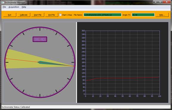
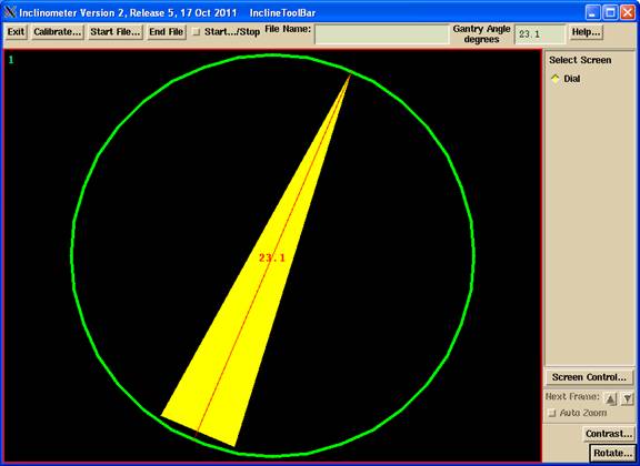
InclineToolBar
The original version of the program used an X/Motif interface. The new version uses a new interface which is shown below, but is otherwise functionally equivalent:
And the Calibrate popup is:
The prior appearance of the program is shown following. The main toolbar of the Inclinometer program is shown below:
![]()
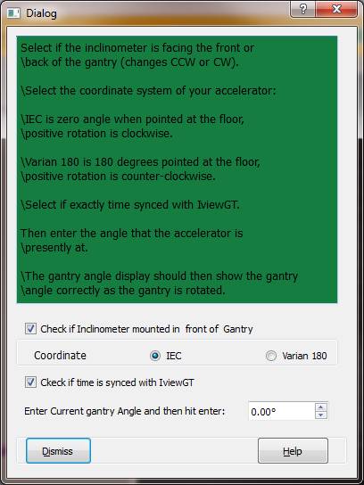
Calibration
First, the user must hit the calibrate button. The calibration pop up is shown below:
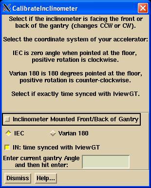
The user must select the orientation of the inclinometer mounting. This can be tested by viewing which way the drawing of the beam rotates as the gantry is rotated. The drawing should rotate the same way, clockwise or counter-clockwise. If the inclinometer is flipped on it mounting, clockwise and counter-clockwise are reversed.
The user must select the coordinate system of the accelerator. IEC is 0 degrees gantry rotation pointed at the floor, positive rotation is clockwise. The standard is positive rotation is counter-clockwise looking down the axis from the positive side. The Y axis is pointing toward the gantry. Hence counter-clockwise is clockwise when viewed from the other side.
Varian 180 is 180 degrees pointed at the floor, positive rotation counter-clockwise.
Set the toggle button in if running on the IviewGT computer, therefore time is synced.
Lastly, the present gantry angle must be entered. Then hit the Dismiss button.
A file is written out to data.d\Inclinometer.dat to record the settings:
/* file
format version */ 2
// calibration
data for the inclinometer
/* gantry
positive rotation +1 is CW, -1 is CCW */ 1.0
/* angle
pointed at floor: */ 0.0
/*
inclinometer mount direction: */ -1.0
/*
inclinometer angle at calibration */ 0.1
/*
calibration_angle */ 0.00
/* gantry
coordinate type: 1 IEC, -1 Varian180 */
1
/* time
sync flag: 0 not synced, 1 is synced to
IviewGT */ 1
This file will be the default for the next time except for the present angle which must be reentered.
The direction of rotation should be tested by viewing the display and the gantry:
Start File
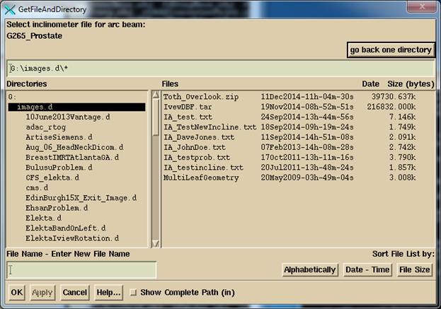
Next the start button should be selected. The directory will defaulted to that in the file InclineDirectory.loc (in versions before 12 Dec 2014, use NewEPIDImagesDirectory.loc) that is in the program resources directory (pointed to by the file rlresources.dir.loc). The user may navigate to another directory or drive by means of the Filter line (type in) or selecting a directory on the left in the GetFileAndDirectory dialog popup shown below:
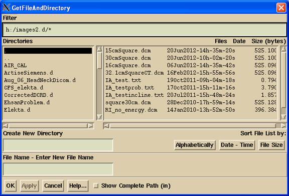
Type in a file name. The file will be prefixed with IA_ and ended with .txt.
Starting and stopping a time gantry angle file
Next hit the Start toggle button to begin recording the time and gantry angle. You should do this before beam on (but after the gantry is no longer moving if not time synced). Hit either the End File button or untoggle the Start…/Stop toggle button to close the file, after beam off
Warning: The gantry must not be
moving before starting if not time synced, as beam on is estimated from the
start of movement.
The resulting inclinometer file will look like:
/* file
format version */ 2
/* gantry
angle versus time for */ <*IA_JohnDoe.txt*>
/* gantry
positive rotation +1 is CW, -1 is CCW */ 1.0
/* angle
pointed at floor: */ 0.0
/* time
sync flag: 0 not, 1 is to IviewGT */ 1
/* Arc
name: */ <*IA_JohnDoe.txt*>
99999
// year
month day hour min sec gantry angle
<*2013 2 7
15 8
9.58*> 23.1
<*2013 2 7
15 8
9.84*> 23.1
<*2013 2 7
15 8 10.09*> 23.1
<*2013 2 7
15 8 10.36*> 23.1
. . .
<*2013 2 7
15 8 26.83*> 1.8
END 99999
This file is to be selected for the VMAT images in the ConvertIMATImages program. If you put the file into the same folder with the image files and select the file with the image files to be converted, it will automatically be read and applied. You should check the angle assigned to the images in ConvertIMATImages.
Program Resource File
In the same program resources directory referred to above is the file InclinometerAngle.dat in which settings can be made concerning the operation of the program. A sample file is shown below:
/* file
format version */ 1
// File
to put tolerance angles for use of the inclinometer.
// Time
between angle measurements when not writing a file in millisec
500
// Time
between angle measurements when writing a file
250
//
minimum change in angle (degrees) for accelerator to have started
0.25
//
maximum change in angle for accelerator to have stopped
//
rotating for three angles in a row:
0.25
The last two parameters are for the situation of the time not being synced.
Program ConvertEPIDImages and ConvertIMATImages
Run these programs to read in the Dicom images written here to convert them to in air x-ray intensity fluence for import to Dosimetry Check. The programs are described elsewhere.