Beam Toobar
|
Beam Toolbar |
Upon creating or selecting a beam from the plan toolbar, the beam toolbar is displayed. The user must first pick the treatment machine with the provided option menu. Thereafter the treatment machine may not be changed. On the toolbar the plan name is shown to the right of the return button. An option menu is next shown for the beam. A different beam may be selected with this option menu among beams in the plan (the current beam toolbar is then popped and the new beam toolbar is pushed). An option menu follows showing the treatment machine, but other choices are grayed out once a machine is selected. Next is an active toggle button. The beam may be selected to be inactive (out), in which case the beam is not normally displayed or computed. The energy is next selected with an option menu. Be careful to select the energy desired for dual energy treatment machines.
Move
Under the Move pulldown are controls to set the isocenter position, the couch, gantry, and collimator angles, and depth of isocenter or source to surface distance.
Move Isocenter
|
Move Isocenter Popup Control |
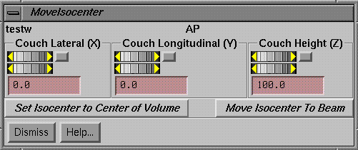
The move isocenter popup provides control for setting the isocenter in terms of couch coordinates. Couch lateral corresponds to the IEC accelerator X axis. Couch longitudinal corresponds to the Y axis and couch height to the Z. Each control has a coarse wheel that changes the coordinate in increments of 1 cm, a fine wheel that changes in increments of 0.1 cm, and a text field where the coordinate can be typed but must be completed by hitting the Enter key. The wheels have areas at each end where they may be moved in single increments with a mouse click, and a home button that resets to zero or the default value for that coordinate.
While the coordinates are changed, the beam will be drawn in frames that are displaying the plan.
A pull down menu is provided to set the isocenter at the location of another beam in the same plan. The isocenter may also be set to the center of an outlined volume.
Move Angles
|
Move Angles Popup Control |
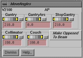
The gantry, collimator, and couch angles may be set here. Also, an arc may be set by setting the Gantry Arc control to a non-zero value.
A pull down menu is provided to set the current beam parallel opposed to an existing beam (including itself) in the same plan.
Set Depth and SSD
|
Set Depth and SSD Popup Control |
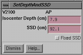
A control is provided set the depth of isocenter or the source surface distance (SSD) of the beam. When specifying the depth or SSD, isocenter will slide along the present central ray to meet the depth or SSD specification. In order for this to happen the central ray must intersect the body skin boundary volume. If the central axis ray does not intersect the body outline, the depth and SSD text fields will be blank. When this control is up, the SSD and depth will be reported as the beam is otherwise moved.
Field size
|
Field Size Control Popup. |
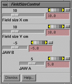
The jaws of the collimator are set with the field size control. If a set of jaws are independent, than separate controls will appear for those jaws. A slider is available for coarse moves in steps of 1 cm, a wheel for fine control in mm, and a type in area is provided. Setting the field size sets a symmetric field size. Use the individual jaw controls for asymmetric jaws.
Options
Multi-Leaf
The multi-leaf control is for machine with a multi-leaf. The presence of a multi-leaf geometry file in the beam data directory signals whether there is a multi-leaf collimator or not.
|
Multi-Leaf Control Popup. |
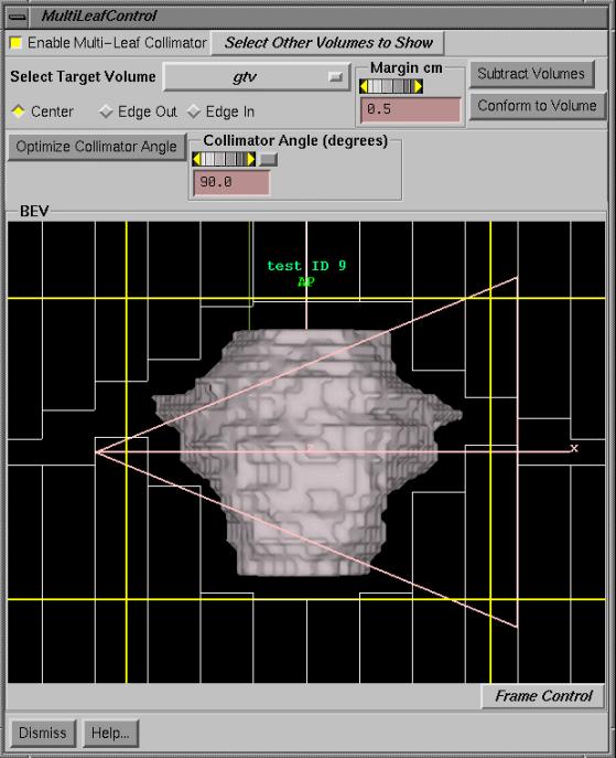
In the upper left hand corner of the control is a toggle button to enable or disable the multi-leaf control. Below that an outline volume must be selected. If a margin is desired, than either use the add margin feature of the Make New Volume From Old popup under the Volumes pull down on the Contouring toolbar to make a new volume with a margin and select that volume, or use the provided control here to specify a margin. The margin is specified in centimeters. If you specify a margin here the volume’s appearance will not change. But the same process occurs. An algorithm is employed that does a convolution of the surface of the volume with a sphere to add or subtract a margin. That modified volume is then projected on to a beam’s eye view plane.
The “Conform to Volume” button will conform the leaves to the projection of the selected volume. There are three options for the leaves. Center means the center of the leaf is moved to touch the volume outline, Edge In means the leaf covers all the space outside of the volume, and Edge Out means the leaf is moved until some part of the edge just touches the volume outline.
There is a pull down at the top of this tool to select other volumes to display in the beam’s eye view display. Selecting a volume will cause it to appear, selecting it again will cause it to be removed from the display. The Frame Control button at the bottom right can be used to select a volume and then change its appearance, such as making it transparent, or drawing a wire frame instead of a solid model view, or to display only the original contours.
If there is a wedge the wedge direction is shown, as shown in the above example. If there is a fixed wedge then there may not be the freedom to consider an optimal collimator angle. Otherwise the collimator angle with the tightest margin can be found with the Optimize Collimator Angle button. The collimator may be rotated from this control.
The left mouse may be used to position an individual leaf by clicking and dragging on the leaf. Be careful not to otherwise click the left mouse on a leaf as it will move to the position of the cursor. The middle mouse will decrease the field of view in the beam’s eye view and the right mouse will increase it (creating the effect of zooming in or out, but the perspective in fact remains at a fixed distance, it is the field of view that changes).
The jaw positions are shown and are positioned as tight as possible. The jaws are modeled as separate entities even on machines that replace one jaw with the multi-leaf. A constraint is enforced that the jaw is aligned with the most retracted leaf.
In the example shown above, a constraint on this particular machine is that a leaf may not be closer than 0.5 cm to the opposed leaf or that on either side of the opposed leaf. These constraints are defined in the multi-leaf geometry file specific to a particular machine.
Subtract Volumes
The leafs of the multi-leaf collimator will conform to the projection of the target volume. One can also select volumes and have their projections with a margin removed from the target volume projection before the leafs are conformed. The leafs are conformed to what is left. Below is the control used for this purpose which is popped up by hitting the “Subtract Volumes” button.
|
The subtract projected volumes control popup. |
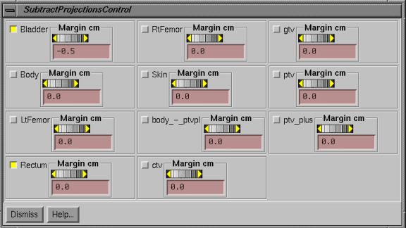
A toggle button and margin control appears for each outlined region of interest. Push the toggle button in to select a volume. Then set any margin if different from zero. The margin is added to the volume if positive, or subtracted if negative, before the volume is projected onto the same plane the target volume has been projected onto. The leafs will conform to the target volume less the projection of all the volumes selected here (after you hit the “Conform to Volume” button).
Wedges
|
Select Wedge Popup Control. |
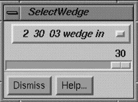
A list is made of all the wedges and their orientations, and are presented to the user as a list of distinct wedges. To select a wedge just select one of the orientations. The label in the option menu shows the wedge number, the wedge angle, and the wedge orientation label as defined in the wedge geometry file in the beam data directory. A smaller wedge angle may be made with any wedge by mixing the wedge with an open field. This is done automatically when the slider is used to select a smaller wedge angle. Monitor unit calculations will then show the monitor units to use with the wedge and without.
Color
The color used to draw the beam can be changed. The color is used when the beam’s toolbar is not displayed. For moving the beam the overlay color used for all drawing is used (if 24 plane graphics, XOR operation is used).
Computed Radiograph and BEV
A computed radiograph and BEV may be selected to be displayed. A BEV is a solid model 3D perspective with
the eye at the source of x-rays. A
computed radiograph may be in the background or may appear by itself. If the beam is moved, the computed
radiograph will be erased.
The computed radiograph is selected under the Options pulldown.
|
Computed Radiograph
Toolbar |
Select an empty frame (by clicking the mouse on the large button
occupying an empty frame). You can
create a screen of empty frames with the Screen Control button (lower right and
side of the main program window).
The contrast enhancement slider will raise CT numbers to the power
selected to simulate photoelectric effect. Four is a good choice. You
can add the computed radiograph (or DRR for Digitally Reconstructed Radiograph)
to an existing BEV for the beam, or create a new BEV with the computed
radiograph as background, or you can show the DRR by itself.
|
Example DRR for an
oblique field. |
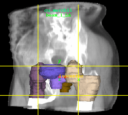
An example DRR is shown below, with corresponding outlined regions of
interest.
The Frame Control at the bottom
of the 3D frame may be used to control objects being drawn.
Utilities
Export 3d Dose Matrix
This option will write out a file that contains an evenly spaced three dimensional dose matrix for the beam. The entries will be in cG/mu. The file is used by program AnalyzeBeam to compare computed dose to that measured with scanning equipment. Computed and measured beam profiles may then be plotted together for comparison purposes. This option is generally used for quality control purposes.
Machine Geometry File
The geometry of the treatment machine is specified in the Geometry file in the subdirectory of the treatment machine. All machines are stored in the directory specified by the BeamData.loc file in the program resources directory. Each machine occupies a subdirectory under that directory and contains a Geometry file.
The Geometry file contains information about the treatment
machine. An example file is shown in
the section on Beam Data. Of importance
here is the definition of directions and coordinates for the treatment machine
parameters. For example, the gantry
angle at which the machine points at the floor and the direction of rotation
that represents an increase in that angle is defined in this file. This file should be edited to fit your
machine. There is also a multi-leaf
geometry file that defines the multi-leaf collimator and a wedge geometry file
for each wedge.