3D Views
This
program provides for three dimensional solid model views. To see these views you must be on a system
that supports Open GL and have 24 graphics planes. Otherwise you will only be able to see wire
frame. The objects seen in a 3d view are
sitting in an xyz coordinate system.
This is referred to as the spatial space. The X, Y, and Z axes are drawn in the view
with the label of each axis at the positive end. Your viewing window is also assigned a
coordinate system. The orthogonal axes
are assigned the labels u, v, and w. The
u axis is horizontal across your screen from left to right. The v axis points vertically upward. The w axis points out of the screen toward
you, the viewer. The origin is at the
center of the screen. The view is
perspective in that objects further away appear smaller. The origin of the u,v,w system in the spatial
system is called the principle point.
Coming out along the w axis toward your eye, the eye position is called
the center of perspective. The distance
from the principle point to the center of perspective is the focal distance.
Creating a Room View
|
Display Room View Popup Tool |
On
the main tool bar go under the Stacked Image Sets pulldown to Display Room
View. Select an image set from the
option menu. Then click the mouse on an
empty frame where you want to show the room view. If there are not empty frames, then make a
new screen by hitting the Screen Control button to the right of your
screen. Screens which do not have a
button in empty frames cannot have anything deposited in those frames. This applies to the screens used to display
all of the images of a stacked image set.
After
you have selected the image set and frame, hit the Apply button.
Window Viewing Controls
Around
the perimeter of the 3d window are wheels to control the viewing angle and
position. The wheels control:
left
bottom wheel: translates the principle
point along the u axis in the spatial system.
The effect is that objects appear to move sideways.
middle
bottom wheel: changes the focal
distance. The effect is that objects
appear to get larger or smaller.
right
bottom wheel: rotates around the current
v axis.
bottom
vertical wheel: rotates around the
current u axis.
middle
vertical wheel: rotates around the
current w axis.
top
vertical wheel: translates along the v
axis.
Controls on the Rotate Pop Up
|
3d View Rotate Control Popup |
When
you hit the Rotate button to the right on your screen you get more controls on
a popup.
Rotate around x, y, z axes
At
the top are controls for rotating the object around the X, Y, and Z axes
respectively.
Theta, Phi, and Twist
On
the pop up your line of sight is converted to spherical coordinates in terms of
theta, the rotation around the Z axis, then phi, a rotation from the Z
axis. Lastly twist is a rotation around
that line of sight, and is a duplicate of the control on the room view
window. The use of spherical coordinates
allows for a system to specify a specific viewing direction. The order of rotation is theta, phi, and
twist for computing these values. You
may specify these angles in any order and you will arrive at the same vector.
The
angles are shown in degrees. We do not
show the angle values around the u or v axes because the axes themselves move
and because the order by which you perform rotations will give a different
result for the same angles. We do not
show an angle of rotation around the x, y, or z axes for this reason also. Rotation around the u and v axis provides an
intuitive system where the object always appears to rotate sideways when
rotating around the v axis, or up and down when rotating around the u axis.
Focal Length
This
control duplicates that on the 3d view window, middle button. The focal length is the distance from the eye
to the principle point. Making the focal
length longer has the effect of making the objects look smaller. The focal length is shown in centimeters.
Field of View Angle
The
field of view angle is initially 25 degrees. As you increase the focal length you will see
more of the object as it appears to get smaller on the screen because you are
moving further away. Increasing the
field of view angle also will make objects appear to get smaller. Changing the focal length changes your
perspective view whereas changing your viewing angle does not. We have picked 25 degrees as a default to
correspond with the perspective of your viewing a 28 cm high screen at a
distance of about 60 cm. The field of
view angle is shown in degrees.
Translate Principle Point
The
x, y, and z translate controls allow you to move the principle point in the
x,y,z object coordinates system. The
principle point is the point in 3 space that you are looking at, and is dead
center in the 3d frame window. The
position of the principle point is shown in centimeters. The focal length is the distance from the
principle point to your eye location, the center of perspective. Theta, phi, and twist rotations are around
this point as well as rotations around the u and v axis. As mentioned above, you can also translate
along the current u, v, and w axes. The
new principle point will be reported in x,y,z coordinates. The u and v controls are on the 3d
window. The w translate control is on
the popup.
Near and Far Planes
For
solid model drawing with Open GL, there is a near plane and far plane. Only points inside the frustum between the
near and far planes are drawn. The near
and far planes are computed as you move your eye location to include the
objects that you are looking at. The
distance is shown in centimeters from the eye location. For wire frame drawn under the X protocol,
the near and far planes have no effect.
You
can toggle off the near/far plane automatic computation if you want to specify
the location of the near and far plane and not have it change as you change
your viewing location. Note that as you
make the focal length smaller, at some point the eye location will have to push
the near and far planes further away to keep them in front of the eye
location. We enforce a minimum distance
of 1 cm to the near plane, and a minimum distance of 1 cm from the near plane
to the far plane.
If
you don't toggle off the automatic near/far control, then as soon as you change
anything else the near and far planes will be moved.
Graphic Aid
|
3d View Graphic Aid Popup |
The
Graphic Aid will show a view of the object and your viewing frustum to further
assist you in understanding where you have put your eye and the near and far
planes. This view point has its own
controls for its viewing location. Your
eye is where the four corners of the frustum come together.
For
further understanding you need to read the Open GL Programming Guide, ISBN
0-201-63274-8, Addison-Wesley Publishing Co., by Jackie Neider, Tom Davis,
Mason Woo.
Light Control
We
have provided complete control over the light model used. To understand the parameters of the Open GL
light model, we refer you to the Open GL Programming Guide whose reference was
given above. We have chosen defaults
which should make it unnecessary for you to mess with the light model or
lights.
|
Light Model Control |
We
have not fully supported all options for Open GL lighting. Open GL guarantees up to 8 lights
supported. Here we provide control for
only one default light. The position of
the light here may only be specified relative to the viewer. Also at this time we do not provide for spot
light control. Otherwise the lighting
equation may be controlled. Normally you
would only provide for a white light, but you do have the controls to make a
colored light. With the light intensity
popups, the top slider will set all three components of the color the
same. Adjusting any of the bottom
sliders will allow for controlling the red, green, and blue intensities
separately.
|
Light Control Popoup |
We
did provide for two sided lighting. You
select two sided lighting under the Light Model. Then for each outlined region of interest, go
under Material Properties if you want to have a different color on the back
side. The same applies for isosurfaces.
Save Frame
You can save the configuration of a 3d room view on an image set under
the Save Frame option. Select Save Frame
under the Frame pulldown on the main menu.
What is saved is the point of view and the frame specific options for
each object that is drawn. This includes
transparency status and clipping planes.
Note that the configuration of 2d images can also be saved with this
tool. You will have to enter a unique
name for each frame that you want to save.
A separate list is kept under each stacked image set. To restore select Restore Frame. Click the mouse on an empty frame on a screen
that you have created.
Material Properties
To
change the reflecting properties of the objects drawn, referred to as material
properties, you must go to the object's control. For region of interest contoured outlines, go
to Contours and then look under Volume:
|
Contouring -> Contours -> Volume
-> Volume Properties -> Material Properties |
Isosurfaces
have a similar control.
Color
and reflectance is a global property for each object. Transparency, wire frame versus solid, etc.,
are frame specific and can be changed under Frame Control for that object for
application in a specific frame. For
more information look also in the above chapter on Outlining.
|
Materials
Properties Popup Control |
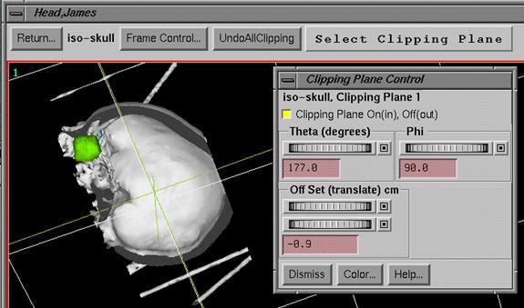
Clipping Planes
|
Clipping Plane Toolbar and Clipping Plane Control Popup |
Outlined
regions of interest volumes and isosurfaces may be clipped. The clipping is specific to the particular
frame and is not a global property for the object. You can specify and position up to six
clipping planes. Any part of the object
on one side of the plane is clipped. Everything
on the other side is not clipped. With
six planes you can clip down to a box of interest.
To
clip an outlined volume select clipping under the Volume pulldown on the
contouring toolbar. Likewise for
isosurfaces look under the IsoSurface pulldown on the isosurfaces toolbar.
On
the clipping tool bar you can select one of six clipping planes at a time. The clipping plane control popup will allow
you to position the clipping plane.
At
the top of the popup you can turn the clipping plane on or off. By default it is off. Turn it on to position the plane. A grid representing the position of the plane
will be shown. Use the Theta and Phi
angle controls to rotate the plane. Phi
is measured from the z axis, and theta is rotation around the z axis. The
angles shown are in degrees.
Given
a position, the Off Set control moves the plane in a direction perpendicular to
the plane with distance shown in centimeters.
There
is a color button that you can use to change the color of the clipping plane
representation. By default, the grids
will be the same color as the clipped object.
Because
a clipping plane is specific to a frame, nothing is saved upon program
termination unless saved with a frame.
Frame Control
Depending
upon the type of 3D frame presented, there will be Frame Control pull down menu
as shown below:
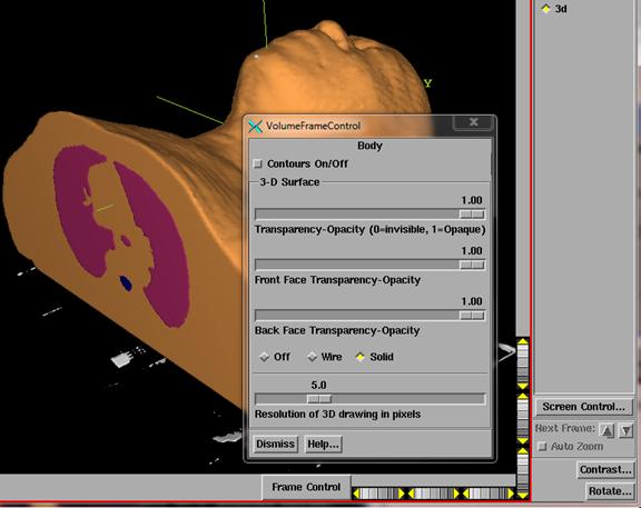
The
top choice will be an Options popup which you can use to change the background
between black and white, or select stereo mode (see below). All structures that have controls for
individual frames that are drawn in the frame can be selected from the list. Individual structures may typically be turned
off or on, or have the transparency mode changed (see above VolumeFrameControl
popup). The options available will vary
with the type of structure, such as a region of interest outline (ROI)
structure or an isosurface for two examples.
On the contouring toolbar there is an option to turn off and on ROI’s
globally.
Stereo
If
you have a stereo graphics card and a means of mapping the output to a left eye
and right eye view, then you can view 3D room views in stereo. Use the Frame Control menu next to the room
view adjusting wheels to select Option.
You will get the below popup:
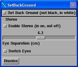 If the Enable Stereo is not
grayed out, you can select stereo. The
control will be grayed out if a stereo visual could not be obtained. The program will draw to a left and right eye
buffer, with a shift corresponding to the distance between a person’s eyes,
here defaulted to 6.3 cm. You can switch
the left and right eye with the Switch Eyes button.
If the Enable Stereo is not
grayed out, you can select stereo. The
control will be grayed out if a stereo visual could not be obtained. The program will draw to a left and right eye
buffer, with a shift corresponding to the distance between a person’s eyes,
here defaulted to 6.3 cm. You can switch
the left and right eye with the Switch Eyes button.