Project Parallel Plane Contour
Tolerance for point elimination
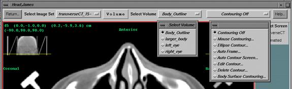
The Pop Up Tool for Body Outlines
Outlining Regions of Interest
Go
to the Contouring pulldown on the main menu and select Contours to get the
contour toolbar.
|
Contouring Toolbar showing also the contouring methods tear off menu
and select volume tear off. |
Contours
around a region of interest are grouped together to form a volume. You must first create and name a volume. Go under the Volume pulldown and select New
Volume. Then add contours to that
volume. The volume is created
considering the contours. The contours
are first sorted into coplanar groups.
Between contours in each group, the shape is interpolated about every
millimeter. A volume is bit mapped for
each group of contours, dividing the volume into voxels and assigning 0 to
voxels outside the volume and 1 to voxels inside the volume. This is called a cuberille. The resulting volume is the union of the
volumes formed from each group of coplanar contours. You can therefore outline a volume on
successive transverse slices followed by outlining on successive coronal
images, for example. This might be
desirable so that a volume has a rounded end instead of a flat end. After the final cuberille is formed, a
surface is generated for the volume forming a connected mesh of triangles.
Because
shape interpolation, bit mapping, and surface generation may take some time,
once you begin contouring an object the generation of the volume is blocked
until you are finished. Turning
contouring off will cause a popup to come up where you can unblock the forming
of the volume. This window provides
other options, such as forming holes, which will be described below.
There
are six tools provided for outlining regions of interest. Four tools for creating contours, one edit
tool, and one tool to delete contours.
Under the Volume pulldown you can delete a volume and change the
material properties of a volume.
All
the contouring tools and most of the functions under Volume pertain to the
volume that is currently selected on the Select Volume option menu. Note also that both the Select Volume option
menu and the contouring tool option menu are tear off menus. You may form a separate window frame around
each and keep them at a convenient place on the screen while you are working on
contours. This will allow you to easily
switch between volumes and contouring methods.
To tear off a tear off menu, hold the left mouse button down on the
dotted line that appears on the pulldown menu and then release the mouse
button. A window frame will form around
the menu. However, when done you should
close the window using the window control on the upper left hand corner of the
window frame.
Most
importantly, the contours are added to the volume that is showing when you
accept the contours, not when you started the contouring.
Mouse Contouring
Selecting
mouse contouring brings up a popup rather than a tool bar. You simply select a frame and begin
contouring with the mouse. The cursor
will turn to a pencil shape and you can either click with the left mouse, or
hold it down and drag. Use the middle
mouse button to back up one point at a time.
A button is provided on the popup to do the same. Likewise you close the contour with the right
mouse or use the close button on the popup.
Closing the contour will cause the contour to connect to the first point
entered. Hitting the right mouse does
not enter a new point. After you close
the contour you can still back the contour up, which will reopen the contour.
|
The mouse contouring popup tool. |
When
you are satisfied with the contour, hit the Accept button on the popup. The contour will be added to the currently
selected volume that is showing on the option menu for selecting volumes.
Project Parallel Plane Contour
As
an aid, you can have projected onto the plane you are contouring contours from
other planes that are coplanar. Each
time you hit the Show Next button, the next closest parallel contour is
projected onto the current frame. These
projected contours can be used for information which you can trace over or
near. Or you may hit the Use button to
select the latest contour shown with Show Next to create a copy in the frame
you are working in. You will be at the
same state with this copy as if you had just closed a contour. Hit the Reset Next to erase all the projected
contours and to allow the projection process to start over again.
Edit Contour
You
may edit a contour once you have closed it by hitting the Edit Contour
button. With the contour editor you can
splice the contour or add and move points.
When you hit the "Accept" button the contour will be added to
the current volume selected as mentioned above, and the mouse contouring tool
will return. Otherwise the edit contour
tool works independent of the mouse contouring tool. See the Edit Contour tool below.
Tolerance
Once
the contour is closed, you can adjust the number of points with the
"Tolerance" scale. An
algorithm is used where by points can be eliminated from the contour as long as
the eliminated point is within the tolerance distance from the resultant
remaining line. A back up copy of the
contour is kept which allows you to adjust the scale either way. However, if you reopen a closed contour with
the "Back up one point" button, the backed up copy is first copied
from the current contour on display.
Accept
If
you don’t accept the contour, the contour will not be added to the volume. Hitting the return button on the contouring
tool bar or selecting another contouring method will cancel the current
contour. Also simply starting to draw in
another frame will cancel the current contour.
BE SURE WHEN
YOU HIT THE ACCEPT BUTTON THAT THE CORRECT VOLUME IS SELECTED. YOU MUST HIT ACCEPT TO SAVE THE CONTOUR.
Ellipse/Circle Contouring
This
tool will create a contour consisting of a circle or ellipse. You may then move individual points or add
points to the contour. This tool can
also be used to project the prior contour made with this tool onto the next
image plane to be used as the starting point for the contour in the adjoining
image plane.
Click
the mouse in a frame showing an image of the selected image set if you do not
currently see a circle afterselecting this tool. Since a circle is a special case of an
ellipse, we may refer to the contour as an ellipse. Below we will simply refer to the contour.
You
can more the contour by dragging with the left mouse button, or you may use the
top wheel controls labeled Horizontal and Vertical. When moving points the wheel controls will
still provide a means to move the entire contour.
|
Ellipse Contouring Popup Tool. |
Below
that you may change the size of the contour and rotate it. Below those two controls are Width and
Height. Either of these two controls
will change the aspect ratio of the contour.
The width refers to the horizontal before the contour was rotated, and
likewise for the height. These controls
initially change a circle into an ellipse.
You
may change the number of points with the Number of Points slider. To see the points push in the Move Points
toggle button. However, changing the
number of points will reset the shape back to an elipse as noted below.
When
the points are showing and the Move Points toggle button is selected, you may
drag a particular point. You may no
longer drag the entire contour.
Note
that moving the Number of Points slider will also do a Reset to Shape
function. The contour will be
regenerated as an ellipse with a different number of points. If you have a really contorted contour to
make, use the Mouse Contouring tool instead.
You can also accept the contour as is and use the edit contour control
to change some part of the contour.
Use
the Add Points toggle button to add additional points to the contour. When you click the mouse, a point will be
added at the mouse location connecting to the nearest line segment that the
point bisets. You should position the
mouse close and next to the line segment that you want to add the point to. If
you hold the mouse down you can drag the point that you just added. But to move other points you must select the
Move Point mode.
Note
that you may change frames with the contour appearing on the new frame.
The
contour is added to the current region of interest volume only when you hit the
Accept Contour button.
Auto Frame Contouring
|
Auto Frame Contouring Popup Tool. |
Use
this method for automatically contouring an area on an image that has a
contrast difference. This tool works on
a designated area whereas Auto Contour Screen below can find all such areas
with the same threshold on all images on a screen.
Threshold value
Here
you click the mouse on each side of the area with a contrast difference. The pixel value is shown at the top of the
popup for each point. This is the pixel
value after the image has been put through the contrast window, as the
contouring is done after going through the contrast window. You may want to first adjust the contrast to
get better separation of the area of interest.
The
threshold value is initially the average of the pixel value of the two points
you click on. But you can adjust the
slider provided to weigh toward one point or the other. Just view the result until you get what you
want.
Tolerance distance
Contour
points are successively eliminated that fall within a tolerance distance. A line is drawn from a point to successive
points, skipping points, until a skipped point would lie outside the tolerance
distance. This procedure reduces the memory
needed for contours and decreases processing time for shape interpolation
later. You can change the tolerance
distance with the slider provided.
Accept button
When
you are satisfied with the contour, hit the Accept button. The contour is added to the volume currently
selected.
Auto Contour Screen
|
Auto Contour Screen PopupTool. |
Auto
Contour Screen is a little more complicated than Auto Frame Contour above with
additional features. Here a threshold
value is similarly determined, but the entire image is search for contours with
the threshold value. Further, the
process may be repeated automatically on all images on the same screen.
Trace value
The
trace value may be found by clicking the mouse on either side of a contrast
boundary, and a slider is available to weight between the two points as in Auto
Frame. In addition you may simply type
in the trace value. Again, here the
pixel values refer to the image after being put through the contrast window and
does not refer to the original pixel value of the image.
Tolerance for point elimination
There
is the same tool as in Auto Frame to control the tolerance for eliminating
points found on the contours (see above).
Keep Contours control
Because
contours are searched for over the entire image options are provided to select
out contours. You may select to keep
only those contours that are not inside another contour with Keep Outside
Contour. That option would be useful for
finding a skin boundary for example. Or
you may select to only keep contours that are inside a contour. In both cases we are referring to contours
found on the same image during this same operation with the same threshold
value, not to any prior contours. Keep
inside contours would be useful for contouring lung where you would want to
reject the skin boundary.
Locate table top
You
can also optionally locate a table top to keep contours from going below some
level (the table top) on all the images.
This can be done on transverse or sagittal images. The level found will apply to all the images
contoured when applying to all the frames on the screen. No contour will be permitted to go below the
horizontal line defined. We realize most
CT and MRI couches are curved, but the option may be more useful when using a
flat insert.
Minimum contour size
There
is also a minimum size that can be used to reject small areas. The default is 1 cm. Type in different values. A contour that does not span this distance is
not kept or shown.
Apply buttons
The
program will not contour anything until you hit one of the two apply buttons. Make selections above the apply buttons and
then hit an apply button to see the result.
Generally you should apply to the current frame only to be sure you are
getting what you want. Then hit the
Apply to All Frames in Screen button to repeat the operation automatically on
all the frames that are part of the current screen.
Accept and Cancel button
After
applying you can either cancel or accept the contours. Hit accept to keep the contours. If you hit the return button on the
contouring tool bar or select another contouring tool, the contours will also
be canceled. If you do this
accidentally, the operation is easy enough to repeat.
Unwanted contours
If
you get some contours you don’t want, you can accept the contours and delete
the unwanted contours later. For
example, in contouring a skull that has a stereotactic frame parts of the frame
may also be contoured. You can delete
and edit out the frame contours with the Edit and Delete tools below.
Edit Contours
|
Edit Contour Popup Tool. |
There
are three methods available to you. You
may splice a new piece into a contour, replacing a segment, you may move
points, or you may add new points to the contour. You may switch between the methods as you
work on a contour. The method is
selected with the radio box at the top of the popup tool.
Selecting a Contour to Edit:
If
you got to the editor from the mouse contouring tool, then a contour is all
ready selected to edit. Upon acceptance,
this contour is added to the currently selected volume, rather then replacing
the contour that was selected as below.
Otherwise first select a frame.
The current frame will have a high lighted (usually red) border around
it. Then click the mouse on the contour
that you want to change. You can only
edit contours that belong to the volume that is currently selected, and the
mouse must be clicked within the pixel distance shown on the slider. You may move the slider to select a different
tolerance distance. Only contours that
lie in the plane of the image displayed may be edited in this manner. When a contour is selected, the cursor will
turn to a pencil shape and the contour will be high lighted in a different
color (the color used when drawing contours).
Splice a Contour
Begin
drawing in the section of the contour you want to replace. Notice that the program will show where the
contour will tie into the existing contour.
From the first point you enter, the closest point on the contour is
found and becomes the first point of the patch that your are drawing.
Continue
drawing in your patch. You may drag the
mouse with the left button down, on click the mouse successively. The middle mouse will back up one point at a
time or you can use the Back Up push button on the pop up tool.
To
end the patch hit right mouse or hit the End Segment button on the popup tool.
You
must now click the mouse on the segment of the contour that you want to delete
and your patch to replace. The resultant
contour will now be drawn. You may now edit
another portion of this same contour by repeating the above starting with
entering another patch.
Move Points
The
points will be drawn in larger splotches than the contour line. If points are on top of each other, you may
have to reduce the number of points first with the tolerance slider. Then simply click on or near a point and drag
it.
Add Points
Simply
click the mouse on the contour where you want to add the point, and continuing
to hold the mouse button down, you may drag the point to a new location.
Tolerance Distance
By
adjusting the tolerance distance you can reduce the number of points on the
contour. An algorithm is used whereby
points are eliminated as long as the eliminated point is within the tolerance
distance of the remaining resultant line.
Once you splice, move, or add a point to a contour, that contour becomes
the orginal contour that the tolerance scale uses to produce a new
contour. Otherwise move the scale back
toward zero will restore the original working contour.
Accept Contour
Finally,
you must hit Accept to keep the changed contour or Cancel Edit to cancel the
change to the contour. If you hit the
return button on the contouring tool bar or select a different contouring tool,
your change will also be canceled.
YOU MUST HIT THE ACCEPT
BUTTON TO KEEP YOUR CHANGES.
Delete Contour
|
Delete Contour Popup Tool. |
First
select the volume that holds the contour you want to delete. You can only
delete contours in the volume currently selected. Then click the mouse on the
contour that you want to delete. The
contour will be redrawn in the overlay color.
Then either hit the delete button to delete this contour, or if you
don't want to delete the high lighted contour you can either hit cancel or
select a different contour by clicking the mouse on a different contour.
The
scale controls how close to a contour in window pixels you must click in order
to select a contour.
When
you hit the Delete Contour button, a confirming message will appear. The confirm toggle button will allow you to
delete a contour without the confirming message, so that you can delete
contours simply by clicking on a contour.
Only use this if you don't need to see the contour high lighted
first. With confirm turned off you can
more rapidly delete contours with single mouse clicks on the contours, but you
have no protection from deleting the wrong contours (except the contour must
belong to the currently selected volume).
Body Surface Contouring
This
pop up is similar to the Auto Contour Screen tool. Here however, we work on images BEFORE they
are contrasted, that is, put through the contrast window, and we specifically
are looking for a body surface outline. If you need to find the body surface
outline on contrasted images, then use the Auto Contour Screen tool
instead. With that tool select Keep
Outside Contours and you will have to define the trace value on a particular
image.
The
automatic body surface outline tool goes across the top of the image and
periodically searches down until the trace value is encountered. Then that contour is traced throughout the
image.
If
you get some contours you don't want, or the contours need some editing, first
accept the contours and then use the Edit tool, or any other outlining tool
such as the Delete tool or Mouse Contouring tool.
The Pop Up Tool for Body Outlines
|
Body Outline Popup Tool. |
Voxel Values
While
the tool is up, you can click the mouse in any frame to get the voxel value,
which is the pixel value of the image before image processing or
contrasting. If the image plane is
between images of the image set and the image was generated with interpolation
on, than the value reported will be an interpolated value. For CT scans, a Hounsfield number of zero
(water density) corresponds here to a voxel value of 1024, with 24 being -1000,
and 2024 being +1000 Hounsfield units.
This tool is provided to assist you in determining a good trace value.
Trace Value
The
trace value is either typed in or set with the slider. A file in the program resources directory,
"AutoBodySurface", sets the default value for the trace value. Contours are traced so that on one side of
the contour are values less than the trace value, on the other side are values
greater than the trace value.
Tolerance
This
sets the amount of error tolerated when reducing the number of points for any
found contour. Successive points are
eliminated as long as the points that are being eliminated are within the
tolerance distance to the new line connecting the two points that span the
eliminated points. Decreasing tolerance
will generate more points and slow down processing with the contours.
Minimum Size Contour
Since
we are finding the body surface outline specifically, we can automatically
eliminate any contours that might wrap around a small object outside the
patient. If the contours is smaller in
size than this value, the contour will be omitted. The default value is 1 cm.
Table Top
You
can set a table top limit using a transverse or sagittal image. No contour will go below the line you
choose. If you set this button you will
be prompted to select a frame. Holding
down the mouse in the current frame will allow you to drag a horizontal
line. Upon release, the line will be
fixed and define a coordinate for which no contour in any of the images may go
below. If you want to find the table
top a second time, simply unset the button and then reset it. This table top tool assumes a flat table top
in that it establishes a horizontal barrier.
Apply Frame
Push
this button to find contours for the
current frame.
Apply to Screen
Push
this button to find contours for all the frames on the current screen.
Accept Contour
Be
sure the volume you want to add these contours to is the current selected
volume showing at the top of your tool bar.
The contours are simply added to the currently selected volume. If you have not made a volume yet, you can do
so while this contouring tool is up.
Select New Volume under Volume on the top tool bar. You should choose a name with body or skin
surface in it.
Cancel Contour
You
can only cancel this operation BEFORE you accept the contours. After you accept contours this tool resets
for a new set of contours. Normally with
only one image set you would only define one body surface volume.
Volume and Surface Generation
|
Unblock 3d Surface Generation. |
3d
surface generation is blocked while in any contouring mode. Selecting Contouring Off or hitting the
Return on the contouring tool bar will exit from contouring mode. A Unblock 3d Surface Generation popup will
appear. The same choices can also be
accessed under the Volume pulldown to redo surface generation. After making any choices on the popup, hit
the unblock or OK button to allow 3d drawing of this region of interest
volume. The 3d surface will be created
when drawing occurs into a 3d frame or when some other function needs the
surface.
The controls on the surface generation popup
|
Surface Generation Controls Popup. |
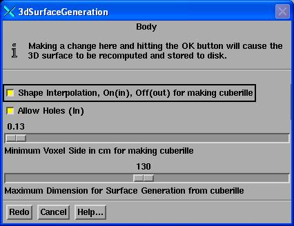
Shape
Interpolation
A
toggle button controls shape interpolation.
Shape interpolation can take some time, up to two minutes, for large
volumes such as the body contour. But
this process occurs only once upon first drawing the 3d-view (and the bit map
is also saved to a disk file for later program runs). Generally leave shape interpolation on unless
you have some reason not to.
Voxel
size slider
Processing
time will also decrease if you increase the voxel size, but you will lose
volume resolution if you do so. The
minimum size of a voxel dimension is constrained here by the pixel size of the
image set, and a default minimum value that is set in the program resource file
ROIvolume. The resolution of the
cuberille determines the resolution for computing a volume in cc (1 cc = 1
milliliter) and for volume histograms.
You may increase the voxel size here with the slider.
Maximum
Dimension for Surface Generation
After
the cuberille is made, the solid surface is generated. The maximum dimension determines what size
cuberille the surface generating routine starts with. If the cuberille from above has a dimension
larger than this value, then the volume will be averaged in that dimension to a
lower resolution. A number here larger than
the default will greatly increase the amount of time to generate the
surface. Only a large volume would be
likely to exceed the default value in any case.
After
the surface is found, the number of triangles in the surface will reduced to
form a lower resolution version of that surface. The system will then pick a resolution to
display according to the size of the triangle that projects onto the
screen. As an object occupies a smaller
area on the screen, a lower resolution of the surface is displayed, which
decreases the drawing time. The number
of pixels that a triangle or rectangular element covers on the screen is found
by projecting the size from the center of the object.
This
means that as lower resolutions are displayed on the screen, details will
disappear. You can control the
resolution that is displayed by going into the contour tool bar and selecting
Frame Control under Volumes. You can set
with the Number of Pixels the resolution that will be drawn, with higher
resolutions being chosen as the number of pixels for a surface element is
decreased. This control is on a frame by
frame basis, and controls for the current frame selected only.
You
might want to have a screen with only 2d views before unblocking more than one
volume to give yourself some walk away time, as the actual generation will
occur when a surface is needed in a 3d frame.
Holes
in Volumes
Normally,
with Allow Holes off, the toggle button out, the inside of any contour is
inside the region of interest. If one
contour is inside a second, the inside contour will have no effect. Another way of saying this for on a given
plane, pixels are marked inside that are in the union of the inside of all
contours on that plane. In this mode you
cannot create a hole inside a volume using only contouring.
With
Allow Holes on, contours are treated differently. If one contour is inside another on the same
plane, the inside contour becomes a hole in the volume. The rule that applies is this, on a given
plane any pixel that is inside an odd number of contours on that plane is
inside the volume. Any pixel that is
inside an even number of contours is outside of the volume.
By
making a second contour inside a larger contour, the second contour will create
a hole on that plane. Shape interpolation
will proceed unaffected.
If
you intend a hole inside a volume, and you also contour on another set of
coplanar planes, then you must also contour the hole on the second set of
planes. The reason is that each set of
coplanar planes is bit mapped and shaped interpolated separately. Then the resulting volume is the union of all
such sets. If the second set of contours
included the same region and did not have a hole, then the hole would be filled
in while taking the union.
Another
way to create a hole is to contour the hole as a separate volume. Then create a new volume as the first minus
the second.
When
allowing holes be careful of the planes you choose for contouring. If two planes are closer than 1 mm, or closer
than the minimum voxel dimension you pick above, than two contours from those
two separate planes may be projected onto the same plane. Thus two contours there were intended to be
outside contours would be projected onto the same plane. The consequences will be that their
overlapping area will become a hole.
New Volume from Other Volumes
|
New Volume from Old Popup Tool |
Under
the Volume pulldown select New Volume from Old.
This is a powerful tool for combining volume, subtracting volumes, and
adding and subtracting margins to a volume.
In
the text field at the top of the popup supply a name for the new volume. Choose a color with the push button to the
right of the name text field. Then on
the left selection box select the volumes that the new volume is to be a union
of. On the right selection box, select
volumes that are to be subtracted. For
example, if one volume were inside another, this method could be used to create
a volume that is the area inside the larger volume less the inside volume.
The
slider may then be used to specify a margin to add or subtract. A positive number enlarges the volume, a
negative number makes the volume smaller.
The new volume is computed by convoluting a ball of radius equal to the
absolute value of the margin. As the
center of the ball sweeps over the entire surface of the volume, the ball
either sweeps out an area to be added to the volume when the margin is
positive, or the area to be subtracted from the volume when the margin is
negative. In this manner the margin is
added or subtract in all three dimensions.
Note that the slider includes a thumbwheel for fine increments and a
text field for typing in a value.
At
the bottom of the popup is an option to produce contours around the
volume. Above we contoured an object and
then created a volume out of it. Here we
start with the volume and produce contours around it. A reason for generating contours would be to
see the contours on 2d images. Otherwise
the volume will only show up on 3d views.
These contours, once generated, can be edited like any other contoured
volume, with the volume then regenerated from the contours.
Volume Properties
Volume
properties can be changed under the Volume pulldown.
Name and Description
You
can change the name of a volume, but the name has to remain unique within the
stacked image set that the volume belongs to.
You can also bring up a text field to type in a description for the
volume.
|
Material Properties Popup Tool |
Color and material properties
There
are two ways to change the color of a volume.
The first is to access Color under volume properties. The color chosen will be for both the front
and back surfaces of the volume. By
default the front and back surfaces have the same color. You may access the material properties popup
which will allow you to change the front surface color or back surface color
separately. You will not be able to see
the back surface unless you turn on two sided lighting in a 3d view frame (hit
the Rotate button and select Light Model).
By default, two sided lighting is off (but the default is controlled by
the LightModel file in the resources directory). To see a back surface you also will probably
have to cut the surface with a cutting plane.
The
material properties besides color that may be specified for the front and back
surfaces are ambient, diffuse, and specular reflectance. These are set the same for all three colors
(red, green, and blue). Emission and
shininess may also be set. The material
properties are discussed in the Open GL reference books.
You
must hit the Apply button to see the effect of changes in the material
properties popup.
Line width
Lastly,
under volume properties, you can change the line width by which the contours
are drawn on 2d images. The contours
will use the front face color of the volume.
Frame Control
|
Frame Control for Outlined Volumes |
For
a particular frame, the appearance of the volume can be changed. First select a frame to make current (by
clicking the mouse in the frame), then select Frame Control. The control will be only for the selected
frame. A popup will come up.
At
the top of the popup is a toggle button for turning contours on or off. On 2d frames the contours will be on by
default. The default is off for 3d
frames (you can display the contours on a 3d view in wire frame). You can change the state with the toggle
button. These are the contours from
which the volume was generated.
Controls that pertain to 3d views only
Transparency
control
The
transparency of the surface can be changed with the slider. Not all systems will support a different
transparency for the front and back surfaces.
The transparency/opacity slider controls how transparent the surface
appears. The top slider sets the
transparency for both the front and back faces of triangles. The next two sliders will allow you to set
the front face and back face differently.
When setting those two sliders the value on the top slider has no
effect, although the average value is shown.
All the way to the left makes a surface completely transparent, and all
the way to the right makes it opaque. Transparent
back faces might not appear transparent on some, or any, systems.
There
are limitations on drawing transparent surfaces. If two transparent surfaces intersect, the
one that is drawn first can be seen inside the surface drawn second. But the one that is drawn second cannot be
seen inside the surface that is drawn first. The same applies for one transparent surface
inside another. Any object drawn inside
a transparent surface or further from the eye location than an intervening
transparent surface after the transparent surface was drawn will not be
visible. For this reasons this program
draws solid objects first, then transparent objects. However no attempt is make to order the
drawing of transparent objects according to which is closest to the viewer,
except that the skin surface is drawn last if transparent. Volumes found with the body outlining tool
are so marked to be drawn last. To avoid
confusion, select only one surface to be transparent.
Off,
Wire, Solid
This
choice should be obvious, controlling whether a solid surface is drawn or just
the edges of the corresponding triangles or rectangles are drawn, or not to
draw the surface at all.
Resolution
Scale
When
the solid surface is drawn, a resolution is picked so that a triangle that
would be situated at the center of the volume will project to the display
window and have a dimension of at least the number of pixels chosen. Lower resolutions are found with a triangle
simplification algorithm that is applied to the triangle mesh that covers the
surface.
As
you move the slider to the right, lower resolution versions of the
triangulation will be drawn. The purpose
of drawing lower resolution is so that as an object gets smaller on the screen,
a smaller number of surface elements will be drawn, increasing the drawing
speed. The default value for this
parameter can be set in the Frame3dDrawable file in the program resources
directory.
When
dragging a viewing control, triangles are skipped so that only a small number
of triangles are drawn.
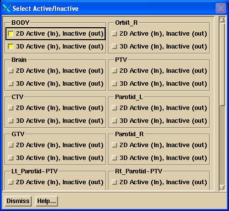
Set Active or Inactive
This
control will allow you to turn a volume off in all frames. There is a separate toggle button for 2d and
3d views. The choice is also saved, so
that when the program is restarted and the same image set is selected, the
drawing of the volume will be governed by the choice previously made here. The setting here not to draw will override
any choice made in Frame Control above.
Volume of a volume
The
volume in cubic centimeters (one cubic centimeter equals one milliliter) can be
computed and displayed. Be aware that
this volume depends upon the pixel size from the original image files read in
from the imaging system. If the imaging
system passed on an incorrect pixel size then the volume calculation will be
incorrect as well, and so will be the scale shown on 2d images. The volume is calculated by simply counting
up all the voxels in the cuberille forming the volume and multiplying the total
count by the volume of a voxel.
Copy Volume
|
Copy Volume Popup Tool |
With
this tool you can copy an outlined region of interest to make a new
volume. You can copy the volume into a
different stacked image set ONLY if the two image sets were fused. This tool is
selected under the Volumes pulldown menu.
Same Image Set
You
will have to give the new volume a different name, since it can't have the
existing name because each volume must have a unique name. Your only reason for copying a volume in the
same image set would be to make some change to it. Note also the New Volume from Old tool that
will allow you to make a copy and add or subtract a margin. Here the volume is copied in all respects
except its name.
Into a Fused Image Set
You
don't have to rename the new volume if the stacked image set that you are
copying the volume into does not all ready have a volume with that name.
Select
the image set that you are going to copy the volume to. Then select the image set you are going to
copy from. A list of the volumes that
are in the "from" image set is than listed. You must pick one of these volumes by
clicking the mouse on that choice. Then
hit Copy.
If
the two image sets are not fused, you will get an error message.
If
the volume name all ready exist in the "to" image set, you will also
get an error message. You will then have
to type in a new name that the volume is to have in the "to" image
set, and hit the Copy button again.
The
new volume will come up active to draw in all 2d and 3d frames, regardless of
the status of the volume copied from.
Hit
Dismiss if you decide not to copy a volume.
Output Contours
|
Output Contours Popup Tool |
This
is an option under the Stacked Image Sets pull down menu, on the Stacked Image
Set Options toolbar. The option will
allow for writing out the contours of the image set in two different forms, 2D
contours coupled with images, and 3D contours.
Select Volumes
The
user must select the outlined volumes whose contours are to be written
out. More than one volume may be chosen.
Write Out 2D Contours
The
first option will write back out the Dicom image files with the contours that
lie within each image spliced into that file.
Note that only contours that are coplanar with and lie on the image
plane will be written out with the image.
Other contours that do not lie in any image in the image set will not be
written out, such as contours outlined on reformatted planes. The contours will be written in the pixel
system of the image with two coordinates per point. Each contour will be labeled with the name of
the outlined volume that the contour came from.
There is a limit of 128 contours per image file under the 50xx group
tag, but you are unlikely to have outlined more than 128 contours on a single
image in the image set.
Write Out 3D Contours
The
second option is to write all contours out into a Dicom file that will not
contain an image. The file will hold all
three coordinates for each point on each contour in the coordinate system
assigned to the image by the imaging system.
The coordinates will be in centimeters.
As Dicom has a limit of 128 contours per file using the 50xx group tag,
more than one file will be written out if there are more than 128 contours in
total. Each contour will be labeled with
the name of the outlined volume that the contour came from.
Output File
The
byte order of the file will be that of the image files for the image set that
were read. A file header as specified by
PS 3.10 will not be appended to the front of the files.
In
either case the user must select or create a directory to write these files to,
and provide a root file name. The file
names will have a comma and number appended to the root name for each file.
Moving an ROI Volume
Simply
pick any two dimensional display of the image set. Click the left mouse on the
frame to make that frame current. Then
click the left mouse any where on that image.
The nearest contour that is also parallel to that plane will be
drawn. As you drag the mouse, the contour
will move. In a plane where the contour
intersects the plane (such as contour from a transverse plane in a coronal or
sagittal view) the intersection of contours will be drawn with that plane. If there are a lot of contours, some will be
skipped for the drawing to improve the draw time. You can change which frame you want to move
in.
Moving Couch Model Example
An
example of dragging a TomoTherapy Couch
ROI volume after selecting it from a template is shown below. On a Windows machine the contour is drawn in
XOR logic as it is dragged. On linux you
will see a red outline (in the overlay planes).
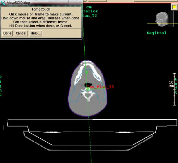
You
will drag the contour to align it with the CT image. Be sure to check a sagittal view and a 3D
view.
In
the sagittal view you will see the intersection of the contours with the plane:
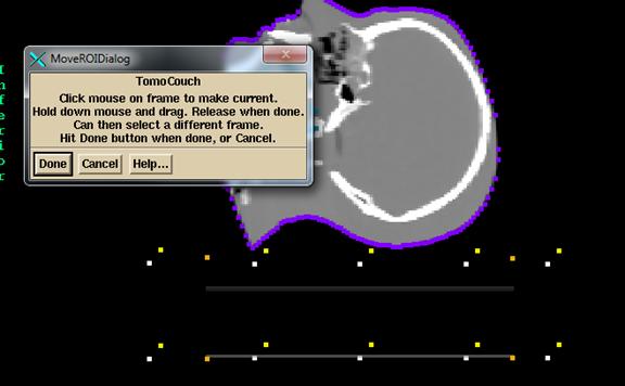
In
the case of a couch model, if the template couch model is not long enough, then
simple go to each end CT scan. Select
Mouse Contouring, hit Show Next, then Use, then Accept, to add the contour in
the plane you are in. Do the same at the
other end CT scan.
The
contours will not be redrawn until you hit the "Done" button.
Beaware
that contours from a prior stacked image set might not correspond to a plane in
the new set, and so will not be drawn anywhere.
Review the ROI volume in a 3D view.
Use frame control to display contours as well as the surface rendering.
A
volume that has no contours cannot be moved.
Nor can the movement be dragged in a 3D view.
Save Volume as Template
This function will copy the
currently selected file to a sub-directory VolumeTemplates.d of the data
directory which is defined by the location file DataDir.loc in the progam
resource directory (in turn defined by the file rlresources.dir.loc in the
current directory where the software is loaded).
Each ROI volume is a
directory, and the directory name defines the name of the volume.
Therefore you can rename the template by renaming the directory for that
template.
Select Template for Volume
This function will allow you
to select a stored template and read it in and add it as an ROI volume to the
currently selected stacked image set. After you have done so, use the Move
Volume on the Volume pulldown menu to move the volume to a correct
location. See the Help button on the move control popup. Be aware,
that a contours from a different image set might not correspond to any CT scan
coordinate in the set you are moving to, and so might not show up (except when
using the move function). Review the volume in a 3D view.
See comments above in Move
Volume if you are copying in a couch model.