To
create a label follow the steps:
To
change an existing label follow the steps:
Copying
Points Between Fused Image Sets
Points, Labels, and Markers
There
are two facilities for locating and label points on images. The points utility locates a point in three
dimensions in a stacked image set. The
point will show up in any image that intersects the point and will show on 3d
views. The label for a point will
appear close to the point. Points are
also used in image fusion. Points are
positioned with a left mouse click.
Labels
are specific to a plane. For a stacked
image set, the label will appear any time the plane is displayed. On other images not part of a stacked image
set, the labels are specific to the particular image. The text for the label may be placed away from the point with a
line drawn to the point. Labels are
position with a button down drag release sequence with the left mouse button.
A
markers is a sequence of connected points.
The marker is assigned a radius and is represented graphically by a
cylinder which following and centered on the points, with joints at the
points. A marker consisting of a single
point is drawn as a sphere.
Points
|
The Points Toolbar and Locate Popup Control |

Points
here are like labels, but the label stays close to the position of the point
and is displayed in both 2-d planes and 3d views of the stacked image set. To be displayed in a 2d view, the plane of
the 2d view must intersect the volume of the point. The point is drawn smaller as the plane intersection approaches
the edge of the point. The distance the
point is from the plane to be drawn is a parameter that can be set separately. Points are displayed as spheres when they
are large enough. On 2d views they will
be circles. On 3d views, small points
will take a diamond shape.
The
points toolbar is selected from the Stacked Image Set pulldown on the main
toolbar. Select Options and then click
on Points on the Options toolbar.
Locating a Point
Click
the mouse on any plane image for the chosen stacked image set. A temporary mark will appear at the position
of the mouse click. You may move this
point simply by clicking again.
You
must than enter a point name. This is
the label that will appear at the position of the point. Note also that a file name is made out of
this label be replacing spaces with underscores. Each label must have a unique file name. The program will not allow you to create a
point name that results in the same file name of another point.
Select
the diameter of the point with the slider.
Larger points will show up better on 3d views but may be obstructive on
2d views. For this reason the diameter
of the point that is drawn is specified separately for 2d and 3d views. A 2d view is an image, whereas a 3d view is
a perspective view.
Because
we are here defining a point in the three space of the stacked image set,
another issue for 2d views is how far can the point be from the plane before it
is drawn. The minimum tolerance is 0.05
cm, to guarantee that round off error will not prevent a point from showing up
when the distance from the point to a plane is computed. Another plane that comes within this
distance of the point will also draw the point. However, the distance from the plane will reduce the radius that
is drawn accordingly. The radius of the
intersecting circle with the plane is used.
A plane beyond the radius of the point will not draw regardless of the
distance parameter. There may be
reasons why you would want to increase this tolerance, but normally you would
not want to change it.
Also
for 2d drawing, you can specify a circle instead of a filled circle. And you can then specify the line thickness
of the circle. This may be useful for
outlining some particular point.
Note
that control is available to control whether points are drawn in 2d views
separate from 3d views, under Control of the points tool bar below.
You
must also select a color for the point.
Once a color has been selected, you may continue to use the same color
for other points that you create without having to reselect the color.
To
create the point whose specifications you have created, you must hit the Accept
Point button. Otherwise hit Dismiss to
cancel or when you are done creating points.
Edit Point
After
a point is created and located, you may edit its characteristics such as size
and color and the text for the label.
The only thing you can’t do is move the point. To move a point delete it and create a new one. Select Edit on the Points toolbar. Then select the point from the list of
points. The edit tool will then pop
up. To change the color of a large
number or all points, use the Control Points tool below.
Delete Point
Select
Delete on the points toolbar. You will
be presented with a list of points.
Click the mouse on the items you want to delete and then hit the Delete
Selected Items button. There will be no
further confirmation.
Control Points
The
control panel will allow you to turn on and off a point in all 2d and 3d windows. This choice will not persist across
termination of the program. By default
all points are shown.
However,
a mechanism is provided to change the color of selected or all points. The color assignment will persist.
Labels
The
labels toolbar is found under the Images pulldown on the main menu.
Here
you can label specific locations on an image.
The label consist
of
a line pointing to a location, that leads to a label.
The
label will only appear on the image you have labeled, or any other copies that
you choose to display. Use Points for
locating points in a stacked image set that you want to see in 3d views. Here labels are specifically only for two
dimensional images.
To create a label follow the steps:
(1) Type in the text for the label in the text
field provided.
(2) Choose a color by hitting the Choose Color
button. Once a color is chosen, it
remains for all additional labels you may create.
(3) Hit the Locate button. Then with the mouse, click and hold down the
left mouse button on the point that you want to point to. While continuing to hold down the mouse,
drag to the location where you want the label to appear. When you release the mouse you will have
created a label.
To change an existing label follow the steps:
(1) Hit the Select button. Then click the left mouse button on an
existing label. Aim for the line
connecting the point to the label. The
label should change color. If you have
selected the wrong label, simply hit the Select button again.
You
can now do one of three things, change the text, change the color,
or
change the location.
1. To change
the text, simply edit the text field and hit the return key.
2. To change
the color, simply hit the Choose Color button and select a new color.
3. To change
the location, simply hit the Locate button and follow the rest of step (3)
above for a new label.
To delete an existing label:
(1) Hit the Select button and select the label
by following the rest of step one above for changing an existing label.
(2) Then hit the Delete button. A prompt will be made to confirm your choice
to delete.
Distances
Distances
between points can be found with the distance function. Under Stacked Image Sets the distance
between two points can span across images in the image set. That is, one can click the mouse to locate
one point on any image in the image set, and click the mouse to locate the
second point on any other image in the image set. Under the Images pulldown, both points must lie in the same
image.
Note that the
distance computed between two points is dependent upon the pixel size read in
the image file.
Copying Points Between Fused Image Sets
This
is accomplished on the Fusion Options toolbar under Stacked Image Sets on the
main tool bar.
|
Copying Points Between Fused Image Sets. |
On
the popup tool, select the image set that the points are to copy to. Then select the image set that the points
are to copy from. The points in the
copy from image set will be listed in the scrolled list area. Select the points that you want copied. Note however, that if a point with the same
label all ready exist in the copy to image set, that that point will not be
copied. Each point, once copied, will
become part of that image set’s list of points independent of the point in the
image set it came from. The points will
be drawn in the image set along with all the other points in that image
set. In the copying process, the
coordinates of the point will be transformed from the coordinates in the copy
from image set to the equivalent location on the to image set using the fusion
solution. Any future change in the
fusion solution will not effect the location of this point. The point will remain fixed until you delete
it.
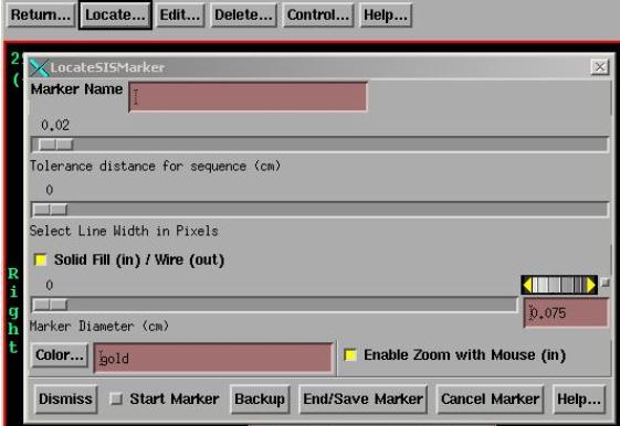
Markers
The
marker toolbar is selected from the Stacked Image Set pulldown on the main
toolbar. Select Options and then click
on Markers on the Options toolbar. The
marker toolbar with the Locate popup is shown below:
You
can trace out and locate a marker with the mouse, edit some properties of the
marker, delete markers, and control their display in 2D and 3D views.
Locate
The
marker is located by clicking the left mouse on each successive point starting
at one end of the marker and proceeding to the other end, although a marker can
consist of a single point. Dragging the
mouse is not supported.
For
a physical object:
If
the marker intersects CT scans at a single point, then follow the marker through
the CT scans, clicking the mouse once on each CT scan at the intersection point
(you might have to first select the frame with the mouse). If the marker appears in the plane of a CT
scan, follow that section on the CT scan, using judgment as to when the marker
center has crossed into the next CT scan space. For a brief section, the center point may be sufficient.
The
marker is assigned a label which will appear with the marker in a particular 2D
plane or at the beginning in a 3D view.
Marker labels must be unique.
The marker label is used for the file name to save the marker and the
text may be changed to produce a legal file name.
The
tolerance distance for the sequence is for the construction of the surface of
the marker at a given radius. Intermediate
points are omitted if the distance of a point from the line connecting an
earlier and later point is less than the tolerance distance.
The
line width selection controls the width of the line in 2D renderings and 3D
wire frame renderings.
The
“Solid Fill/Wire” toggle button controls whether the marker is solid filled on
2D renderings or just a wire outline.
The
marker diameter controls the diameter of the rendered marker in 2D and 3D
renderings.
The
color controls the color of the marker.
To
enter a marker, hit the "Start Marker" toggle button and begin to
click the left mouse, starting at one end and proceeding to the other end. The middle mouse button will back up one
point at a time or use the "Backup" button on the locate popup. The "End/Save Marker" is used to
close the marker and save it in a file.
The right mouse button will also close and save the marker. A point is not added with the right mouse
button. But with the “Enable Zoom with
Mouse” button in, the middle mouse and right mouse will invoke the zoom
function of the image frame rather than backup one point or end the trace. Leave the Enable Zoom button in if you need
to zoom in on a particular spot. The
middle mouse button with zoom in the image with the center where you click the
middle mouse button, the right mouse button will zoom out. You can change the Enable Zoom button during
a trace.
The
Cancel Marker button can be used to cancel a marker that has been started. Cancel is also effected by unselecting the
start toggle button.
Edit
All
the properties of the marker can be edited except the position of the points
that define the marker. Delete the
marker and reenter it to change the points.
Delete
You
can select markers to delete.
Control
You
can select specific markers to turn on and off in 2D and 3D views, and you can
change the color of all selected markers as a group. There is otherwise no individual frame control for a marker.