Selection of a stacked image set
Stacked Image Set
Definition
A
stacked image set consists of a series of images taken sequentially without
patient motion along an axis of the body.
All the images must be coplanar, but need not be the same size. A stacked image set may consist of all
coronal, sagittal, or transverse images, but not a mixture. It is necessary that each image be specified
in relationship to some common coordinate system. The Dicom standard requires this for all
images in the same series. Such images
are here considered stackable to form a three dimensional model of the
patient. Normally you would only pull the
images from a single series. However,
the capability is provided to pull images together from anywhere, as might be
the case if a body technique changed to a head technique when the head is
encountered. However, the head images
must be specified to the same coordinate system as the body images in this
example and so should be part of the same series. The program has no way of knowing the
relationship between different series, and the user must not combine images
outside of a series unless it is known apriori that all the images meet the above
conditions. CT transverse scans may be
taken with the gantry rotated, as long as all images are parallel to each
other. The program will not allow
non-coplanar images to be together in a stacked image set. Nor may two images occupy the same plane
within a stacked image set.
Coordinate System
Each
image file must consist of patient orientation information and the coordinates
specifying the plane of the image relative to a common patient coordinate
system. Dicom 3 specifies that positive
Z axis pointing towards the patient’s head, with the Y axis pointing down (for
a supine patient) in the posterior direction, X axis to the patient’s
left. Be aware that this program uses
the IEC coordinate system with the positive Z axis pointing anterior, Y axis toward
the patient’s head, and X axis to the patient’s left. Dicom 2 and 1 specified images relative to
the imaging equipment, not the patient.
In that instance we must rely on designations within the file as to feet
first or head first, supine or prone.
New
To
create a stacked image set select New under Stacked Image Sets on the main tool
bar. A name unique to the patient must
be provided by the user. A patient may
have any number of stacked image sets.
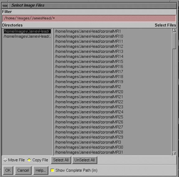
To select images for a stacked image set, the program will provide a
file selection box starting at the directory specified in the file
NewImagesDirectory.loc in the program resource directory.
Choosing
a directory on the left of the popup will show the files in that directory on
the right. Navigation is also possible
with the filter function at the top of the popup. Note on the bottom that the files may be
copied or moved into the patient directory.
Moving means that the file in the images directory will be erased after
it is successfully copied into the patient’s directory under the new stacked
image set name. The entire file is
copied or moved unchanged.
|
Select Images Files for a Stacked Image Set Popup |
Normally
you should configure your Dicom input so that a patient’s series is stored in a
separate directory under the new images directory.
After
you have selected all the images for a stacked image set, the images will all
be displayed on a screen.
Computed Scout Views
For
stacked image sets with more than one image, a coronal, sagittal, and
transverse scout view is computed. The
plane for these scout views is through the center of the volume of the image
set. Each scout view is computed by
considering parallel (non-diverging) rays through the image set and averaging
the pixel value of the pixels that the ray goes through. Pixels with a value less than a threshold
specified in the program resource file ComputedScoutImages are not
averaged. This is to reduce the dynamic
range of the resulting image.
Upon
display of a new image set, the computed scout views may be useful in locating
errors due to patient motion during the imaging process, as discontinuities may
result and be discernable in the scout views.
Orientation Labels
For
each plane displayed, the edges of the image will be labeled among anterior,
posterior, superior, inferior, right, and left.
To see the labels you may have to enlarge the frame or an image to full
screen by hitting the button in the upper right hand corner of the frame. The text for these labels comes from the
program resource file PatientOrientationLabels (under the language
subdirectory). For oblique planes the
labels may be combined for the dominate directions, such as Ant-Sup.
It
is absolutely essential that the orientation labels on the two dimensional images
be verified. Although one is unlikely
to confuse anterior and posterior, left and right is another matter,
particularly in the head and pelvis.
Even in the thorax, there are rare individuals whose organs are reversed
left to right from the norm.
We strongly
recommend that a protocol be established with the imaging center to place a
marker consistently on one side of the body to eliminate any possibility of
confusion between left and right.
If patient
orientation is critical in any way, you must have some means of verifying the
correctness of the orientation shown on the image display.
As a corrective measure you may flip the stacked
image set across any of the three orthogonal planes in a x,y,z coordinate
system. However, be extremely cautious
if you do so, as it is unlikely that the display would be wrong. An error would have to been made during the
imaging process in specifying the patient orientation to the imaging system,
such as a patient placed feet first instead of head first but specified as
being head first. Or an error occurred
in writing out the Dicom files.
Do not flip an
image set unless you know precisely where and what caused the orientation
labels to be wrong and that you know precisely how to flip the image set to
correct the error. It would not do to
create a mirror image of the patient, or create an error when there was none,
or create a different error.
Be
sure the labels are correct before you do any further processing.
As
an aid, routine rlDicomDump is provided to dump the contents of a Dicom image
file, with decoding of some pertinent fields.
Type rlDicomDump followed by the file name to read. rlDicomDump may be found in the subdirectory
tools.dir.
Edit
You
may edit an image set at any time.
However, we recommend that you complete the image set before any further
processing is done. Otherwise confusion
may result, for example, if an outline is made on an image but then the image
is deleted from the image set. Besides flipping an image set as described
above, you can delete an image from an image set if there is some reason to do
so. Normally you would want the most
complete model for the patient, but an image file may have been corrupted or
mistakenly included in the image set.
Edit
Stacked Image Set Toolbar shown with the Flip Image Set Popup
You
may also add images to the image set.
But, as noted above, these images must be stackable, taken of the
patient during the same imaging process without patient motion. This function is provided as a means to
correct a situation where all the images were accidentally not included in the
original selection of the image set.
Selection of a stacked image set
The
program allows for displaying more than one image set. Consequently, through out the program there
are instances where an image set must be specified. For example, in reformatting an image the
program has to know which image set the image is to be reformatted from. Be careful of situations where an image set
is selected and then a new tool bar is pushed.
You will operating on the selected image set.
Stacked Image Set Options
Controls
are found under the Stacked Image Sets pulldown on the main menu and are
described throughout this manual.
Under
Options is the Options toolbar.
|
Stacked Image Set Options Toolbar |
The
options selected here are covered under the appropriate chapters in this manual
for the particular topic that is selected for each choice presented in the
toolbar.
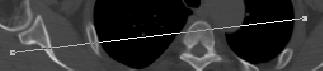
Distance Tool
The
distance tool under the Stacked Image Sets pull down will compute the distance
between any two selected points. You
click the left mouse on the first point and then on the second. The two points do not have to be on the same
image but do have to be two points in the same stacked image set or between two
fused image sets.
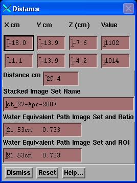 In addition to computing the geometric
distance between the two points, the water equivalent path length is also
computed. The first instance is the water equivalent computed path length based
upon the CT number to density conversion curve.
The path is computed in the stacked image set that the first point was
in. The second text box below that is
the water equivalent path also taking into account the density of any ROI
volume that the path might have gone through that had been assigned a
density. The ratio between the geometric
distance and the water equivalent distance is then also shown in the text box
with the water equivalent path. In this
example shown here, the path did not transverse any ROI volumes that had an
assigned density.
In addition to computing the geometric
distance between the two points, the water equivalent path length is also
computed. The first instance is the water equivalent computed path length based
upon the CT number to density conversion curve.
The path is computed in the stacked image set that the first point was
in. The second text box below that is
the water equivalent path also taking into account the density of any ROI
volume that the path might have gone through that had been assigned a
density. The ratio between the geometric
distance and the water equivalent distance is then also shown in the text box
with the water equivalent path. In this
example shown here, the path did not transverse any ROI volumes that had an
assigned density.
The
distance tool under the Images pull down on the Main Toolbar, simply computes
the geometric distance between two points on the same image.