MarkRT
(VGRT)
Math Resolutions, LLC
5975 Gales Lane
Columbia, MD 21045
Version 2, Release 14
16 May, 2007
Copyright 2005, 2006, 2007
by Math Resolutions, LLC
Program finds small adjustments to the couch position.
Accelerator Couch Coordinate System
Definition of the Markers and Isocenter
Reading in of the treatment plan
Definition of the Markers from the
CT Scan Set
Typing in Marker and Isocenter Coordinates
Default Coordinate System for Data
Entry
Read in Radiographs and Locate X-ray Fields
Beam’s Eye View Coordinate System
Pixel Size and Source Image
Distance
2)
Locate Axes Points: X-, X+, Y-, Y+
3)
Locate the Field using a Template.
Couch Coordinates for Radiographs
Solve for Isocenter of the
Radiographs
Trace Marker on Radiographic Image
Standard Deviation in Image Plane
Maximum Gantry Angle Difference
Isocenter in Plan Coordinates
Manual Method
Number of Decimal Places to Show
Medical Accelerator Geometry File
Introduction
This program is provided to precisely position a medical accelerator’s isocenter relative to a patient prior to radiation therapy treatment. This is accomplished by implanting one or more markers inside the patient, locating those markers relative to an image set and the isocenter of treatment beams, and tracing the images of those markers on radiographs taken prior to each treatment session. Because the markers may be long and flexible, they are located in the image set with this software by tracing their visible path thought the image set, typically a set of stackable CT scans. The markers are then retraced on two or more radiographs taken at the time of treatment. The location of isocenter within the image set for the radiographs is found, and the couch coordinates for each treatment beam is then reported given the couch coordinates for the radiographs and the known isocenter of the beams relative to the image set.
The
user of this software must test this patient location system before clinical
use. A test procedure is provided by
the distributor of this software.
This software is built upon System 2100 from Math Resolutions, LLC, a radiological image display system, and uses the plan and beam functions from Dosimetry Check, also from Math Resolutions, LLC. Reference will be made to specific sections in the manuals of those two integrated products. This program includes all the functions of System 2100 and can optionally include all the functions of Dosimetry Check if turned on with the license key. Otherwise only those Plan and Beam functions necessary for patient positioning will be available from Dosimetry Check. On line manuals or downloadable PDF files are available at www.MathResolutions.com.
This program is available for Microsoft Windows or Linux personal computer systems, or for Silicon Graphics Irix computer systems.
Running the Program
Run program MarkRTTasks, shown below, as a convenience to select and run the programs provided for the multiple functions required. The program interface is shown below. You can simply leave this small window up.
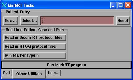
The “Other Utilities” pull down:
Making a selection here runs a separate utility. As a convenience you can pre-select the patient here. But for daily operation of MarkRT while treating patients, make the patient selection from MartRT instead as the program will then directly push the locate patient toolbar. The programs selectable here are described below. For reading in the plan from the planning system or otherwise to enter markers and define an isocenter, you would start with “Read in a Patient Case and Plan”.
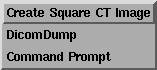
Other utilities provides a program to create a CT scan of a water density square, a utility to view the information in a dicom file, and to get a command prompt window.
Program finds small adjustments to the couch position.
The
patient should be immobilized during this entire procedure.
You should first closely align the patient with isocenter using the existing tools to accomplish this, such as the laser alignment system on the treatment machine. Here we will solve for small adjustments as indicated by the markers. The final couch movement found here should therefore be small. If a large couch movement is called for, then the patient position must be reviewed. Beam films can be taken to confirm the position of isocenter to compare to the plan. Setting the isocenter to the beam in the “Trace and Solve” popup below should result in exact alignment of the marker images and their projected images with the new images.
Patient Orientation
Program normally assumes that
patients are treated head first toward the accelerator gantry unless otherwise
indicated. Care must be taken for a
feet first orientation. The same
precaution should be taken for a prone patient.
You can change the orientation of the patient from the plan toolbar (see the Dosimetry Check manual). The ReadDicomCheck program for the Dicom RT plan download should mark a patient feet first (FF) for each if the Dicom plan file indicates the patient orientation as being feet first. Head first or feet first is a beam attribute, not a plan attribute. Here we will require all beams to have the same orientation.
You cannot change the orientation between supine and prone as you would normally scan the patient supine or prone. Prone patients will be shown prone.
The RTOG protocol is another matter. The protocol is somewhat ambiguous and contradictory. It is stated that the Z axis always points toward the patient’s feet, but the coordinate system is right handed. Then that the X and Y axes refer to the treatment machine and not to the patient, yet scans are to be viewed from the patient’s feet, and that the Z axis depends upon scan order but is to point toward the patient’s feet. Sample RTOG files we have received for a feet first plan were not encoded correctly.
For the rare situation of feet first or prone, you should first test in a phantom and determine a protocol.
Accelerator Couch Coordinate System
The IEC coordinate system is used for the plan tabletop coordinate system of this software. With the gantry pointed toward the floor, the coordinate system is for the X axis to go to your right as you are standing in front of the couch looking into the gantry. The Y axis will be parallel to the axis of rotation of the gantry and points toward the gantry. The Z axis points from isocenter up toward the ceiling.
The direction of the positive couch X, Y, and Z axis in the treatment machine’s coordinate system will be specified in the Geometry file relative to the plan tabletop coordinate system and in the CouchCoord file. X is always associated with the lateral, Y with longitudinal, and Z with height. The Geometry file must specify the directions of the actual coordinate system of the couch relative to the plan tabletop system. The CouchCoord file must also specify the correct directions.
The
Geometry file only supports coordinate systems for the couch in which
differences in a coordinate will represent differences in distance, and a
coordinate defines a unique location of the couch. This coordinate system is used for all couch movement controls
for moving isocenter within a plan.
The
CouchCoord file is used to provide support for non-coordinate couch systems and
is be used to convert delta movements and initial couch coordinates to actual
read out numbers. This file is NOT
needed if your couch coordinates IS a coordinate system.
In a coordinate system, a point 1 cm negative to the origin will be represented by –1.0 and a point 1 cm to the positive side of the origin will be represented by +1.0. The Geometry file described below will govern the conversion of plan tabletop coordinates to actual couch coordinates for movement of isocenter. The direction of the machine’s couch coordinate system relative to the plan tabletop coordinate system is specified in the file. A constant may be added to the plan tabletop coordinate system so that, for example, the origin might display the number 100.0 if the constant value of 100.0 is specified.
The
direction vectors from the Geometry file are used if there is no CouchCoord
file in computing the couch coordinates of each beam given the couch
coordinates at which the radiographs were taken and the movement needed. Otherwise the CouchCoord file parameters
are used for displaying the final couch coordinates.
We have noted unusual systems. Such as on the Elekta machines, the couch lateral will read 1.0 if 1 cm to the right of the origin (to your right while looking into the gantry) and will display 99.0 if 1 cm to the left of the origin. This is not a coordinate system by our definition since the distance from 99.0 to 1.0 is 2.0 cm, not 98.0 cm. Further, in theory, 50 cm could be either 50 cm to the right or to the left. Confusion is only avoided by knowing that the couch will not move that far. If the lateral couch coordinate was reported to be 0.2 cm and the couch must be moved -0.4 cm (to the left in the negative direction), MarkRT (VGRT) will report the lateral couch coordinate for the beam as at –0.2 cm if there is no CouchCoord file. In the room the couch will read 99.8 cm at this location. Since the operator must be familiar with the machine’s readout and has to make such translations under normal use, there should not be any additional confusion here. The same idea applies for couch longitudinal and height movements.
If the CouchCoord file is present, the parameters in it will be used to convert to the new coordinate. In the example above, the coordinate will now change from 0.2 cm to 99.8 cm for a delta of –0.4 cm.
Definition of the Markers and Isocenter
The position of the markers and isocenter of a beam must be known in the same coordinate system. There are two ways to accomplish this. One is to download the treatment plan and CT scans to this program. The markers are then traced through the CT scan set to define them. The isocenter of beams is known from the plan download.
A second method would be to locate specific points using what ever tools are available on the planning system and to reenter those points. The points must include the markers and at least one beam isocenter. This latter method might be more convenient for point markers as opposed to linear markers. Immediately below is the downloading of the treatment plan method.
Reading in of the treatment plan
Because the location of the treatment plan’s isocenter must be known relative to the stackable image set, means is provided to download this information from the radiation therapy treatment planning system, or to otherwise locate isocenter within the image set. Both the RTOG and Dicom RT protocols are supported for reading in the image set and beam geometry.
RTOG, Dicom RT
Two separate utilities are provided to read plans and images from the radiation therapy treatment planning system. See the “RTOG Download” and “Dicom RT Download” sections in the Dosimetry Check manual for details. These two utilities will read the plan and create a patient entry in the patient directory of this system, and store the image set as a stacked image set under the patient entry, and store the plan under the patient entry. See the note above in regards to patient orientation, particularly in regards to the RTOG protocol.
A stacked image set is a group of successive slices that together models the patient anatomy in three dimensions. A patient entry may have more than one stacked image set associated with it, and may have more than one plan. Each plan is linked to a stacked image set and may have more than one treatment beam. After running either utility to create the patient case, run program MarkRT (VGRT) and simply select the patient and plan that was created. For the RTOG or Dicom RT download, the user should select the image set and beam geometry to be downloaded from the planning system. Region of interest (ROI) outlines can be read and optionally displayed by MarkRT (VGRT) in 2D and 3D views, which may prove useful.
Recreation of Plan
If for some reason the plan is not available in RTOG or Dicom RT format, the plan and beam positions can be recreated with MarkRT (VGRT). However, the images used for the plan must be available in Dicom format. Images, such as CT images taken consecutively through the patient are here referred to as a stackable image set, meaning that the images are geometrically related and can be used to define a 3 dimensional patient volume. In MarkRT (VGRT) create a new patient and create a new stacked image set. Read in the images for the stacked image set. Refer to the System 2100 manual sections on Patient and Stacked Image Sets to perform these functions.
In order to position a beam, a skin outline must exist. Go under Contouring and select the auto-body outlining tool. See the System2100 manual.
Next, create a plan and then a beam for that plan. Position the isocenter of that beam in the correct location within the stacked image set (see “Beam” in the Dosimetry Check manual). If there is more than one isocenter in the plan, you may optionally create a beam for each isocenter. The only parameter that matters here is the isocenter of the beam. Other aspects of beam geometry are not used here. You may use the default accelerator provided when creating a beam. It is important that you review the Geometry and CouchCoord files for that accelerator (see below).
Definition of the Markers from the CT Scan Set
Because the markers may be more than points, they are traced here with MarkRT (VGRT) in the stacked image set. Upon running MarkRT (VGRT) select the patient and then select the stacked 1Gimage set.
The markers must be visible in the stacked image set in order for you to trace them. You must assign a name to each maker, if there is more than one, and trace each one with the mouse through the stacked image set. This function is covered in the “Points, Labels, and Markers” section in the System 2100 manual. This tracing will define the marker in the coordinate system of the stacked image set. The markers are then drawn in 2D plane images and in 3D perspective room views. The marker facility is found under the Stacked Image Sets pull down menu on the main toolbar (shown below), to Options, to Markers.
Typing in Marker and Isocenter Coordinates
Coordinates defining the markers and isocenter can be entered directly if they are known in the same coordinate system (IEC or DICOM) relative to the patient. They might be found by locating the markers on the CT scans using the mouse on the planning system, along with the isocenter of a beam. These points would have to be written down and then reentered here. This program’s coordinate system is IEC. The +Y axis points towards the patient’s head, Z axis is up superior, X is the patient’s right to left. In DICOM the +Z axis points towards the patient’s head, X is the same, and +Y axis is down inferior. The program will provide the option of typing in the coordinates in DICOM if your planning system is DICOM. Otherwise you can enter directly in IEC coordinates. You are going to have to know and review your planning system’s coordinate system to know how to enter the coordinates.
Default Coordinate System for Data Entry
There is a file called VGRTTypeIn in the program resources directory that will set the default system used to enter the points here. An example file is shown below:
/* file format version */ 1
// file to specify default coordinate system of the planning system.
// 1 is IEC, -1 is Dicom
-1
Note that there is only one parameter to set, IEC or DICOM. This will preset the choice in the marker and beam isocenter entry popups shown below. Points entered in DICOM will be converted to IEC.
Program MarkerTypeIn
The type in facility is a separate program called MarkerTypeIn. Run this program to enter you data. The main toolbar for this program is shown below:

You will first have to
select or create a patient entry. Then
you will have to create or select a plan.
The current plan name will be shown in the text field on the tool bar. Then you can enter markers and beam
isocenters. You can also delete a
marker or a beam, or delete an entire plan.
When done use the “Show Plan Entries” under the Plan pull down menu
to review your entries for correctness.
For each plan you create, a stacked image set will be made with no images. A simple model of the patient will be created to distinguish the superior and inferior directions on the drawing of the accelerator when a solution is found.
Type in a marker
For a new marker you will get the marker type in popup tool shown here:
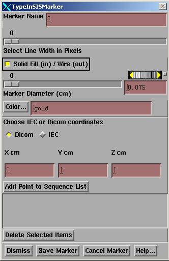 You
must specify a unique name for the marker.
The line width selection controls the width of the line in 2D renderings
and 3D wire frame renderings. The
“Solid Fill/Wire” toggle button controls whether the marker is solid filled on
2D renderings or just a wire outline.
The marker diameter controls the diameter of the rendered marker in 2D
and 3D renderings. The color controls
the color of the marker. See the
section “Points, Labels, and Markers” in the System2100 manual for more
details.
You
must specify a unique name for the marker.
The line width selection controls the width of the line in 2D renderings
and 3D wire frame renderings. The
“Solid Fill/Wire” toggle button controls whether the marker is solid filled on
2D renderings or just a wire outline.
The marker diameter controls the diameter of the rendered marker in 2D
and 3D renderings. The color controls
the color of the marker. See the
section “Points, Labels, and Markers” in the System2100 manual for more
details.
You must pick whether you are entering the points in DICOM or IEC with the radio box. Then type in each coordinate in centimeters in the provide field, one for X, Y, and Z. Then hit the “Add Point to Sequence List” button. If this is a point marker, you need only enter one point. If a linear marker, then you must enter a sequence of points in order that will define the center line of the marker. When you are done hit the ”Save Marker” button. Beforehand you can delete a specific point.
Type in a beam isocenter
Enter a beam isocenter by selecting “Add Beam” from the beam pull down menu. You will get the below TypeInBeam popup:
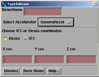
You must enter a unique name for each beam if more than one. Then select the accelerator. This selection specifies the directory the program will read for geometric information about the treatment machine. See the below sections on the geometry and couch coordinate files. All beams must be for the same treatment machine and this is strictly enforced in program MarkRT (VGRT).
The proper selection of DICOM or IEC must be made here. A change in selection by the above marker type in tool will cause the same selection here and vice versa, along with a warning message. Type in the coordinates and then hit the “Save Beam” button. Under the beam pull down menu you can delete a prior beam entry. These beams will all be stored with nominal angles which are of no interest or consequence here.
Show Plan Entries
When
finished entering the markers and beams, select “Show Plan Entries” on the plan
pull down menu for review.
The coordinates for all the markers and beams isocenters will be shown for review for correctness in both IEC and DICOM coordinates, and can be printed.
Locate the Patient
Shown below is the main toolbar of the System 2100 library functions that is the top toolbar for MarkRT (VGRT):
![]()
If there is only one plan the program will automatically sequence through the below tool bars after selecting the patient to arrive at the Locate Patient tool bar shown below. If you need to first trace markers on the CT scans, then hit the Return buttons to back up to the main tool bar.
The path you must take will initially be shown in green. You must first select the patient under the Patient pull down. The program will automatically select the next toolbar if there is more than one plan for this patient. Otherwise under the Applications pull down on the main toolbar, select MarkRT (formally VGRT). The first time this tool bar is selected, the Retrieve Plan function will automatically be implemented. If there is only a single plan, it will be selected. Otherwise you will have to select the plan. Otherwise select the plan on the plans toolbar. The plan will be retrieved and the plan toolbar pushed. The stacked image set is also read but not displayed since it is generally not needed and so why wait those few seconds for those images to come up. However, if you do need those images displayed just return to the main toolbar and reselect the stacked image set. Shown below is the plan toolbar (this is the Dosimetry Check plan toolbar):
![]()
The first time the plan tool bar is selected; the program will push the Locate Patient toolbar. Otherwise select Locate Patient to get the locate patient toolbar. But note that on the plan toolbar there are functions under the Beams pull down to created a beam if the plan had not been read in as described above.
Shown below is the locate patient toolbar which you will use to locate isocenter from radiographic images of the markers:
![]()
The first time you select this toolbar, the program will create a new screen with two empty frames for you to display your images in. You select one an empty frames as the location where you want to display the next image file by clicking the mouse on one of the buttons occupying an empty frame, such as 1 shown below. The color will change to the armed color after selection. The first frame is selected automatically.
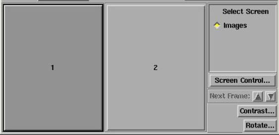
If you are going to enter more than two images, then hit the “Screen Control…” button shown above and on the “Screen Properties” popup below select the bottom to “Change Screen Layout”:
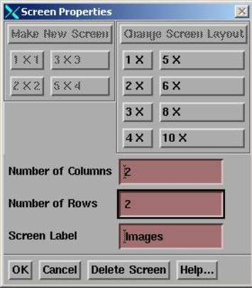
Then type in the number of rows and columns you want. Here we show two columns and two rows of frames selected. Hit the OK button and the screen layout will change to a layout of 2 by 2 frames. You can always change the layout of any screen any time.
The sequence of operations is to read in the radiographs under the “Field Image” pull down menu. Then to specify the gantry angle and couch angle (if non-zero) for each image on the locate field tool (shown below) also under the “Field Image” pull down menu. If the images were from x-ray film it will also be necessary to locate the beam’s eye view coordinate system on each image. The default distance to the image plane may be optionally chosen to eliminate having to type in the distance on each locate field tool as shown below. If the images are from an EPID, you are probably done with this function.
There
should be at last two such radiograph images taken at close to a right angle
(90 degrees) to each other.
If the angle is less than 60 degrees you will get a warning message. The couch coordinates cannot be solved for accurately if there is a small angle between the radiographic images. There will be separate warning messages if the angle is less than 30 degrees and then again if less that 15 degrees. However, you are not prevented from using a single image, for an example an AP image, to adjust the couch lateral and longitudinal coordinates.
The makers will be projected onto the radiographic images read in here. The “Marker 3D Display Control” will enable you to turn those images on and off, and also an option is provided to select to project other ROI’s onto the same images. This projection is a solid model central point perspective view. If the couch coordinates are correct, along with the rest of the image geometry, the projected marker images will be on top of the radiographic marker images.
The “Trace and Solve” tool provides the method for you to trace in the image of each marker on the radiographs and then solve for the couch coordinates.
The “Markers” button will push the markers toolbar that is also under Options on the Stacked Image Sets pull down menu on the main System 2100 menu.
Read in Radiographs and Locate X-ray Fields
Read in the X-ray Image
You can select to read an image file. The available formats are Dicom, TIF, and PNG. For Elekta, the pixel size is not written to their Dicom files so a separate entry is provided here with a defaulted value of 0.025 cm. We can also read images files written by Radiological Imaging Technology Inc. software should you scan images with their software. Otherwise you can use the Imaging program that comes with Windows XP with any film scanner that has a twain driver, such as the Vidar film scanner. Further details, if needed, can be found in the Field Dose section in the Dosimetry Check manual.
Locate X-ray Field
The locate x-ray field popup tool is shown below:
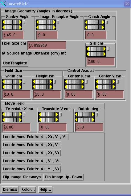
This tool provides methods for specifying the geometry of the radiograph and for locating the beam’s eye view coordinate system if necessary. The tool displays an X,Y axis and field outline according to the field geometry set here.
An example appears below:
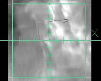
You must locate the x-ray field in terms of its coordinate system, as well as define the gantry, image receptor, and couch angles at which the picture was taken. For the case of using an EPID, it will probably only be necessary to specify the gantry angle used for the radiograph.
Beam’s Eye View Coordinate System
The IEC coordinate system is used for the beam’s eye view. At zero angle the X axis of the beam's eye view coordinate system is parallel to the couch lateral (when the gantry is pointed at the floor) from your left to right while looking into the gantry, or the patient’s right to left if the patient is head first supine. The Y axis of the beam's eye view coordinate system is parallel to the gantry axis of rotation and is positive toward the gantry. The z-axis of the beam's eye view system is positive up toward the source of x-rays.
Gantry and Couch Angle
The gantry and couch angles must be entered for each x-ray image made. The angle directions and nominal angles are defined in the Geometry file (see below for an example) for the particular machine in the machine data directory. [The machine data directory is defined by the file BeamData.loc in the program resources directory. The program resources directory is defined by the file rlresources.dir.loc in the current directory. Each treatment machine is in a separate directory in the machine data directory.] The Geometry file must be reviewed and edited to correspond with the actual coordinate system of the medical accelerator. Here only the gantry angle, couch angle, and couch lateral (x), longitudinal (y), and height (z) coordinate system matters. For the couch x,y,z coordinate system, what matters are the directions defined for positive and negative motions as described below. The CouchCoord file is used for computing actual readout numbers.
Normally, you will probably not rotate the couch from its zero position.
Image Receptor Angle
The image receptor angle is not the collimator angle. Rather it is any possible rotation around the central ray and the positive direction (increasing angle) is counter-clockwise when viewed from the x-ray source. The image receptor angle is only needed if you are letting the x-ray field define the beam’s eye view coordinate system and either the image receptor has actually been rotated or you have rotated the collimator.
If the image receptor is to define the beam’s eye view coordinate system, then you need not be concerned with this angle unless it is actually a device that has been rotated.
If the image of the radiation field is to define the beam’s eye coordinate system, you will have to use the image receptor angle to specify the collimator angle if you rotated the collimator. So for convenience, normally do not rotate the collimator but leave it in its zero position. If you do rotate it, enter the angle as the image receptor angle, but keep in mind that the image receptor angle is positive counter-clockwise when viewed from the source. If your collimator rotates in the opposite direction, you will have to change the sign of the angle entered here.
For an EPID, you can let the image receptor define the beam’s eye view coordinate system and so you need not be concerned about the collimator angle nor the image receptor angle. Just leave it zero.
If using an EPID, the EPID must remain centered.
Pixel Size and Source Image Distance
The pixel size and source image distance must correspond to give the correct magnification in the plane of the image. With an EPID, although the EPID might actually be at a further distance than 100 cm, the distance here can be stated as 100 cm as long as the pixel size reflects the actual pixel size at a source distance of 100 cm. Adjust the source image distance (SID) if necessary to correspond to the distance the image was measured at. Note that there is a mechanism for defaulting this distance to something other than 100 cm. See the file BeamFilmHolders file below.
If the pixel size of the image was picked up in the image file, you should not have to change it. If the pixel size was not in the image file, then type in what the pixel size was. If the image has 40 pixels per inch, for example, then the pixel size is 2.54cm/inch / 40 pixels/inch = 0.0635 cm. The drawn field size should agree with the image when the SID and pixel size are correct. Not all image formats require the pixel size be entered. It is optional in TIF for example.
Likewise the SID is often not in the image file. If it is, that distance will be set here.
Locating the X-ray Field
The rest of the locate field popup is like the one in Field Dose for Dosimetry Check except here there is no need for a margin around the field. These controls are needed if the image of the x-ray field is to be used to locate the beam’s eye view coordinate system. These controls are not needed if the image receptor defines this coordinate system and the central ray is always at the center and properly rotated with the correct SID and pixel size.
If
using an EPID, the EPID must remain centered on the central ray.
The
radiographic images must be viewed from the x-ray source side of the image.
Normally you would locate the x-ray field, which is to define the beam’s eye view coordinate system, before proceeding to trace the markers and solve for the couch position. The beam’s eye coordinate system is defined above.
The beam’s eye view coordinate system must be properly
located on each image to accurately solve for the couch position.
There are three ways to locate the x-ray field. These are:
1) Translate and Rotate
Use the “Field Size”, “Central Axis At”, “Translate” and “Rotate” controls to locate the radiation field if the central ray and orientation is not known. First use the "Field Size" controls to set for the opening of the field in centimeters to that for which the radiograph was made. By the opening we mean the distance between the collimator jaws at the defined distance, typically 100 cm, for accelerators (this is also defined in the below Geometry file).
If the field is not symmetric, use the "Central Axis at" controls to locate the central axis. The central axis is moved relative to the center of the field opening, that is, here the origin is the center of the field opening. You will have to know how the asymmetric field was set up.
Once you have properly defined the field size used for the radiographic image, you should then translate and rotate the drawn field using the corresponding controls to correspond to the image of the radiation field.
2) Locate
Axes Points: X-, X+, Y-, Y+
If the X and Y axes are marked, for example with pin pricks, you can alternately use this method. After hitting this button you are expected to click the mouse on a point on the X axis and then a second point on the X axis that has a greater X coordinate. Then you are to click on a point on the Y axis and then a second point with a greater Y coordinate. The cursor will change for each point, <- to indicate the first (left in beam's eye view) X axis point, -> for the second X axis point. \|/ for the first Y point and /|\ for the second Y point. You can also enter three points instead of four. Select the appropriate button for the combination of three points that you can enter, and enter them in the order shown.
3) Locate the Field using a Template.
A template would be something in the beam with defined points that you can locate with the mouse on the radiographic image. Using the template, you will solve for SID, rotation angle, and location of the central ray. You must still set the correct gantry angle. Further, it is assumed that the central ray is perpendicular to the image plane. You must also flip the image beforehand if viewing from the wrong side (patient side instead of source side).
A file called BeamTemplate must exist and reside in the machine’s data directory. There must be at least three points. An example of a file follows here:
/* file
format version */ 1
// file
to define the beam template for the machine
/*
distance in cm source to definition plane of template */ 100.0
/*
number of points to follow */ 4
// x
y cm
-10.
0.0
10.
0.0
0.0
-10.0
0.0
10.0
//
diameter to draw a point in cm
0.5
//
color to use for grid.
<*spring green*>
//
color to use for points when unselected:
<*dodgerblue2*>
// color
to use when selected:
<*orange red*>
Note that you can define the coordinates at some distance other than 100 cm. The colors are from the file ScreenColors.dat in the program resource directory. Upon selecting the Use Template button, there will be an additional popup that will display the relative location of the template points, as shown below:
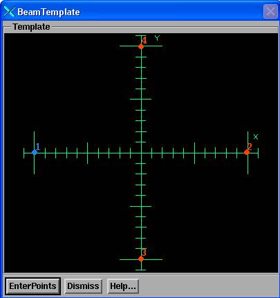
You must then hit the EnterPoints button. The color of the points will change to the selected color. Then you must click the left mouse on the image of each point on the radiographic image in the same numerical order. Upon the last point the program will solve for the SID and transformation (shift and angle) and the field grid will redraw and the controls on the Locate Field popup will show the new found values. Upon dismissing the Locate Patient toolbar the image will reformat to be centered and horizontal.
Flip Image
There is also a flip image button. You should be looking at the field image with your eye at the source of the radiation. Use this if an x-ray film were scanned flipped over.
Color
The "Color..." button is for changing the color of the drawn outline after you dismiss this control and the field outline is no longer being moved. During movement, for 24 plane true color graphic systems, drawing is done with an XOR operation. Adjust the contrast to dark or white so that reversed darkness is easy to see as gray areas may not appear different.
Drawn X-ray Field
Radiation field must be located properly to be able to solve for the couch coordinates. The gantry, couch, and image receptor angles, and the SID must have been entered correctly.
Rather than dismiss this tool, if you select another frame that has an image present, the tool will be popped up to allow you to locate that field on that image. This will save you from having to return to the pull down menu for the next field to locate.
Using Prior Case Run
If you save each day’s program run (see Save and Retrieve below), the program will automatically restore the settings from the prior run for each new image. This includes the all angles (gantry, couch, image receptor), SID, field size, and prior central ray location. However, the pixel size from the current image is always used. The images must be taken and read in the same order as the prior program run. This provides a convenience to not have to constantly reenter the same information. However, the anything that has changed must be updated and the central ray and field orientation may have to be relocated. Likewise, the prior traces will be read in and displayed. The prior traces can be deleted, or moved to match the present radiographs (see the below Trace and Solve section) if moving the trace to the image of the marker is sufficient.
Auto-Image Read In
The program has a function that will automatically read any new image files that appear in the new images directory. This directory is specified by the file NewImageDirectory.loc in the program resources directory (which is in turn specified by the rlresources.dir.loc file in the current directory from where you run programs).
After a case is done and stored, the directory where the prior images were read from is searched for the new image files.
The functions of the auto-read in is controlled by the below file VGRTAutoGetImage in the program resources directory shown below:
/* file
format version */ 1
// file
to control timeout function to read in new images.
/* Auto read of images on (1), off (0) */ 1
/* Time in seconds to check for new images,
every */ 10
/* number of seconds image may be old */ 600
/* number of images to read before turnoff of
auto read */ 2
/* type of dicom file: 0 general, 1 Elekta (no
pixel size) */ 0
The first entry after the file format version turns this feature on or off. The second entry control how often the program checks for a new file. This happens only when the locate patient toolbar is the current toolbar. The next entry specifies how old an image file can be, here defaulted to 10 minutes. Older files will be ignored. The next entry will turn off the auto read in after the specified number of image files are read and displayed, regardless of how the image file is gotten (here or above by selection). The last parameter may be used to specify an Elekta machine, which does not write the pixel size to the Dicom file and must be defaulted. The auto-read in function is only supported here for Dicom images files.
Volume and Marker 3D Control
The Marker 3D control is used to turn on and off the projection of the markers onto the x-ray radiograph plane, and to select other objects to be projected. The popup tool is shown below:
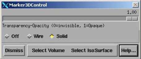
Select among Off, Wire, or Solid. The slider is used to change the transparency of the marker for the solid view. Note that the diameter of the markers are set in the properties of the marker (see the Points, Labels, and Markers section in the System 2100 manual).
You can select regions of interest outlines (ROIs) and isosurfaces to be displayed as well under the “Select Volume” pull down. The first time the volume is selected it is display. The second time it will be selected to not be displayed. When displayed, properties such as transparency are accessible from the “Frame Control” pull down in the lower right hand corner of the 3D view display window.
The markers, ROI’s and isosurfaces are projected onto the radiographic images. If all coordinates are known correctly, the projected images should coincide with the radiographic images.
Trace and Solve
The trace and solve popup tool enables you to either manually align the projected markers with their images on the x-ray radiographs, or to formally solve for this alignment. Only the couch coordinates may be changed to achieve alignment, and assuming that you have correctly specified the gantry, image receptor, and couch angles, the image distance, and that the beam’s eye view coordinate system has been properly aligned. The trace and solve popup tool is shown below:
The trace and solve popup will rearrange its couch input fields according to the VGRTShowBeams file described below and is shown with a different presentation here:
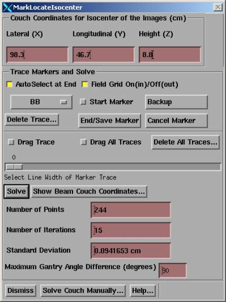
Couch Coordinates for Radiographs
At the top of this popup you must type in the present couch coordinates at which the x-ray pictures were taken. The couch coordinates for each beam will then be solved for relative to the coordinates entered here. What is solved for is where the isocenter at which the radiographs were taken is relative to the CT scan set. Here the coordinates for that isocenter are entered here in the couch coordinate system. Knowing where a beam is relative to the same CT scan set, the beam position in couch coordinates can then be computed.
The
couch must remain at the same location while the radiographs are taken.
Solve for Isocenter of the Radiographs
What must be solved for is where the isocenter for the radiographs was relative to the stacked image set, the CT scan set (do not move the couch during making those images). From that isocenter location and the location of the beams, both known within the CT scan set, the shift needed for each beam can be computed and applied to the couch coordinates typed in.
Trace Marker on Radiographic Image
You may want to adjust the contrast of an image first to increase the visibility of a marker. You might also want to use the edge enhancement feature of the contrast control to also increase the visibility of maker. Slide all three sliders of the edge enhancement control on the contrast popup to the right and the hit the apply button. Then adjust the contrast of the edge enhanced image.
You may also want to zoom an image before tracing. The middle mouse button will zoom in (the center will be where you click the middle mouse), the right mouse button will zoom out. Do this before you start the trace.
Select a marker with the option menu, and then trace that marker on each of the images. On each image, turn the "Start Marker" toggle button on (in) and begin tracing with the mouse. The middle mouse button or the "Backup" button can be used to back the trace up one point at a time (with only two mouse buttons hitting both will simulated a middle mouse button). After completing the trace, the right mouse button or the "End/Save Marker" button may be hit to end the trace. The trace will be redrawn in red on that radiographic image.
The
correct marker must be selected on the Select Marker option menu when the
"End/Save Marker" function is invoked. If auto-select is on, the option menu will advance each time the
marker trace is saved.
A scale control is available to increase the line width of the final drawn marker trace.
The "Cancel Marker" button may be hit to cancel a trace that has been started.
Use the Delete button to delete and erase the trace of the currently selected marker in the image frame that is current (the current frame is outlined in red). There is also a control to delete all the traces.
Be sure to always trace every marker from end point to end point. This includes tracing the marker through the CT scan set. Suppose for instance one were to trace all 6 cm of a 6 cm marker. But on the radiograph only trace 1 cm. Along the long axis of a straight marker, the 1 cm section could align anywhere along the length of the marker with an uncertainty of 5 cm in that direction. The solution below could show a zero standard deviation, yet one coordinate could be off by 5 cm.
The
trace for each marker must match and lie on top of the corresponding image of
the marker on each radiograph to solve for the couch coordinates accurately. Upon solving, the projected markers should
also correspond.
Drag Traces
On each image you can drag the traces to fall on top of the image of the respective markers. You can drag the traces collectively or one at a time. This function can be used when the prior program run traces are picked up from the last saved case to save time. If the trace cannot match the image, then delete the trace and re-trace it.
Select the corresponding toggle button. Depress the left mouse button and drag with the mouse button down. Upon release the trace is replaced with its new location. When dragging an individual trace, you must press the mouse close to the existing trace. It will snap to the mouse location and you can further drag. Upon release of the left mouse button, the drag operation is terminated. You may start another drag operation if you do another left mouse press within 15 seconds. Otherwise the drag toggle button will go back to an off state.
Solve
To solve, hit the solve button. The program considers the distance from each point generated every millimeter along the traced marker to the image of the marker projected onto the same image plane. The minimum distance from each such traced point to the projected marker is found (using the center line of the marker, not its diameter). The couch coordinates are found that will minimize the sum of all these distances squared.
In mathematical terms, the software solution considers in the image plane the sets of two coordinate sequence pairs, one is the trace of the image of a marker, call it set I, and the other the sequence of points of the corresponding marker that have been projected onto the image plane, call it P. Each is a sequence of (x,y) coordinate pairs that define a sequence of points on the image plane, and the marker shape in both cases is estimated by connecting each consecutive sequence of points with a straight line.
I = {(xi,yi)} for i from 1 to n points that were traced on the image plane. From this sequence, generate more points between successive points on the line segments connecting successive points so that the distance between points is not more than 1 mm (an arbitrary distance to use). We have the now the set of points I’ = {(xi,yi)} = {ti} for i = 1 to o, where o >= n, and ti is a two dimensional vector.
And for the projected sequence, m points defining the marker in three space are projected onto the plane of the radiographic image to produce m two dimensional points on the images plane. P = {(xj,yj)} = for j from 1 to m. Let Sl,l+1 represent the line segment from (xl,yl) to (xl+1,yl+1).
Let D be the function returning the distance from point ti to the line segment Sl,l+1 where this distance is either to the nearest end point among (xl,yl) and (xl+1,yl+1) or is to the perpendicular bisector of the line segment if the perpendicular bisector is between the end points of the line segment.
The measure Mk of the distance between the two
sets of points is defined as:
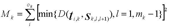
where we use k here to designate one of the trace – projected pairs among all those on all the available image planes. We may continue to sum over all marker pairs over all image planes for a total of q such pairs of sequences, k counting from 1 to q:
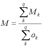
The couch coordinates (lateral, longitudinal, height) is searched that will minimize the sum of M. The square root of M is reported here as the standard deviation. This form of the solution is used to consider the case of a marker changing shape from when the original CT scans were made. In that case a best fit is found according to the definition of M above.
Standard Deviation in Image Plane
The standard deviation of the distance (in cm) computed above for the solution is reported, along with the number of points generated (sum of ok), and the number of iterations performed to generate the solution. The translate controls will be updated and the location of the radiographs to reflect the current solution. The smaller the standard deviation, the better the solution was. A perfect match in the image planes would have a standard deviation of zero.
The
standard deviation is for the two dimensional distances in the plane of the
images and does not necessarily reflect how close isocenter has actually been located
in three space.
As noted above, one could have a zero value of the standard deviation yet a very large error in the actual solution if the entire length of a marker were not traced. Also, if the marker has changed shape, the fit parameter could be large yet the solution good. A warning will be displayed if the standard deviation is larger than a preset threshold. The default threshold is 0.5 cm and 1.0 cm. A more severe message is displayed if larger than the second threshold. The user may change the threshold in the below file.
See the below error analysis for things that can effect the accuracy of finding isocenter. A visual inspection of the images is necessary to assure the projected and traced markers are aligned.
Threshold File
The file with name “VisiThreshold” will set the threshold to the users choice for two messages. If the first threshold is reached, message one will be displayed, if the second is reached, a second message more severe will also be displayed. The file is in the program resources directory located by file rlresources.dir.loc in the current directory. An example of the file format follows:
/* file
format version */ 2
//
threshold for first warning in cm
0.5
//
threshold for second more severe warning in cm
1.0
//
threshold for comparison to yesterday's move in cm.
0.3
The third
parameter is to set a threshold for signaling a popup warning if the movement
in any direction was different by the distance specified here, defaulted to 0.3
cm. This warning message comes up upon
selecting the display of the couch coordinates below.
Maximum Gantry Angle Difference
The maximum gantry angle seen between images used in the solution will also be displayed. Separate warning messages will be generated if the angles are less than 60, 30, and 15 degrees. The radiographs should be close to 90 degrees apart. However, it is possible to use only one file if, for example, you wanted to use an AP film only to adjust the couch lateral and longitudinal coordinates only. In that situation you should use the manual controls.
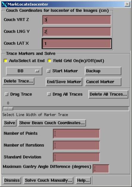
Isocenter in Plan Coordinates Manual Method
You can move the isocenter of the radiographs within the stacked (CT) image set manually with the popup control you get with the “Solve Couch Manually…” button above, the popup control shown below:
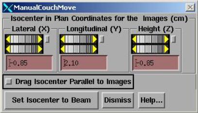
The
location of isocenter for the radiographs is displayed in the plan coordinate
system of this program. The couch
system shown here is specified in the Geometry file for manual movements.
This is in the plan tabletop coordinate system and is the internal coordinate system of this program, not your planning system. The tabletop coordinate system is IEC as described above. But the couch coordinates shown here is the couch coordinate system specified by the Geometry file for movement in plan coordinates. The CT scan set is known relative to this coordinate system. You may initialize the isocenter of the x-ray images in plan tabletop coordinates to that of the isocenter of a beam with the “Set Isocenter to Beam” pull down menu. You can manually move the coordinates of isocenter in plan coordinates to visually align the projected markers with the radiographic image of the markers (select "Marker 3D Control" to control projecting the markers). However, we recommend that you use the solution method described below.
You can also drag isocenter with the mouse in a plane parallel to each radiograph. Select the Drag function by depressing the Drag toggle button shown above. Select a frame with a radiographic image and then depress the left mouse and holding the left mouse button down, drag the mouse. You will see the marker’s move correspondingly. However, we are actually moving isocenter in the OPPOSITE direction that you move the mouse in this plane so that the marker’s will appear to move in the same direction as you move the mouse. Iterating moves between two orthogonal radiographs can accomplish a solution.
Selected ROI’s or
isosurfaces will also drag with this function.
However, fewer triangles are drawn during the drag to facilitate the
speed of drawing.
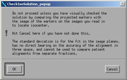
Display Couch Solution
You
must first look at the radiographic images to verify that the projected markers
now lie on top of the image of the same markers.
To display the couch coordinates of each beam, hit the "Show Beam Couch Coordinates" button. First you must have entered at the top of this popup the couch coordinates when and where the x-ray images were made. The couch coordinate for isocenter for each beam will then be displayed (and you can print this) relative to the entered couch coordinates. See details on the couch coordinate system above.
For the first beam in the beam list, the movement is displayed. This is only shown once since you would only move the couch once. If further beams have a different isocenter, then the couch coordinates shown reflect the couch coordinates to move to.
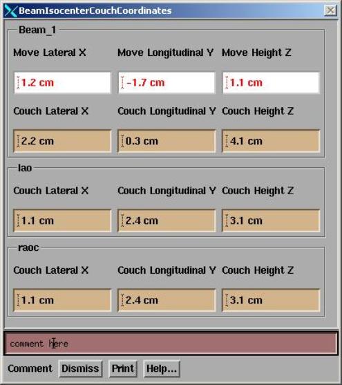
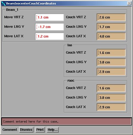
The display may take four different forms depending upon setting in the VGRTShowBeams file that is in the machine data directory for the particular treatment machine. The coordinates may be arranged horizontally or vertically, in the order of x, y, z, or z, y, x, and labels for each axes may be assigned. Shown below are two examples of the show beams popup:
The
couch translation directions in the Geometry file and/or CouchCoord file for
the particular medical accelerator must be correct to display the correct couch
coordinates of each beam.
An example of the VGRTShowBeams file, Geometry file and CouchCoord file are shown in a below section.
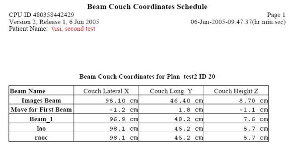
Isocenter of all beams are typically at the same point, but we do not want confusion should a plan be done with different isocenters. Hence the final isocenter couch coordinates for each beam is presented. Shown below is an example of the beam schedule printout (for horizontal display in x,y,z order). The couch coordinates for the images that the user entered are first shown, then the movement for the first beam in the list, then the coordinates for each treatment beam:
There is a comment line at the bottom of the show beams popup. A comment entered here is saved with the case and will be display on the above beam couch coordinates schedule printout and on the beam move summary printout. If the case has been saved, the comment will automatically be resaved if changed.
Number of Decimal Places to Show
Normally by default, the movement is shown to the nearest 1/10 cm, that is, 0.1 cm or 1 mm. However, if for some reason you want to see the movement to two decimal places (in cm), then use the VGRTDecimalPlaces file in the program resources directory to specify two decimal places. If this file is not present, the default is one decimal place. The contents of the file are shown below:
/* file
format version */ 1
// choice of 1 or 2 decimal places to show on
move.
1
Use WordPad if on a Windows system to edit this file and change the 1 to a 2 in the last line. Be sure to save the file to its original name. Don’t add .txt to the file name. The final coordinates of the couch will continue to be shown to the nearest 1/10 cm however, only the movement amount will be shown to 2 places.
Save And Retrieve
You can save your work under the SaveAs button on the locate patient toolbar (under File). You will be prompted for a name to save under. This name is actually used as a directory name, so illegal file name characters will be stripped out.
There is an automatic save mode as well. If the file VisiAutoSave is present in the program resources directory (pointed to by the file rlresources.dir.loc in the current directory) then the auto-save function is on. The file can be an empty file and a template file VisiAutoSave.off is provided. Just rename the file VisiAutoSave. Upon hitting the return button on the locate patient toolbar, the case will be saved using a date and time stamp for the name. If further changes are made upon reentering the case, the case will be saved again under the same name upon hitting the return button. You can at any time hit the SaveAs button and select a new name. But you will otherwise not be allowed to save to an existing case name.
The case is also saved if the auto-save function is on when the show beams popup is dismissed. This guarantees that the show beam move summary report will include the current case if that function is selected before returning from the locate patient toolbar (but has to be selected after the show beams popup).
However, note that the comment is saved if changed if the case has been saved.
To retrieve a case, select the retrieve button (under File) and select the case. A separate popup will appear with the case. This is so that the present case is never confused with a retrieved case. You can make changes to a retrieved case but can only save to a new name.
The locate cases are saved in directory lp.d under the plan name which is under the directory ckpn.d which in turn is under the patient’s name in the patient directory.
Upon the next run of the program, the latest saved case is used to default the field location for each image and the traces. The images must be read in the same order to maintain the proper default settings. Otherwise the corresponding parameters can be reentered.
Summary of Couch Moves
Under File you can get a history of all prior moves. A file will be written to the temporary file directory and the history can be printed. And example printout is shown below:
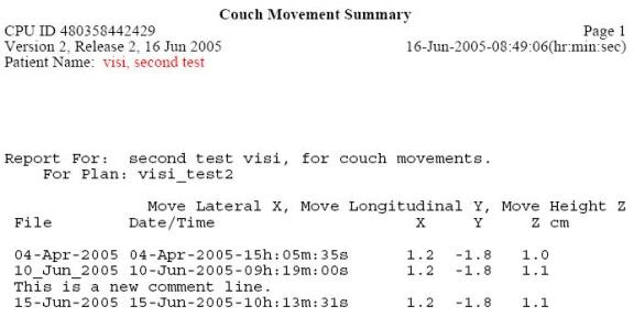
For each row is shown the first 11 characters if the name the case was saved under, followed by the date and time of creation. The delta moves are then shown in cm. Any comment entered for a case is written about the case line.
Error Analysis
Errors in geometry will effect the final result. Here we will give a review of the uncertainties that will effect the final result, and is not intended as a final tabulation of all sources of error.
The accelerator isocenter will wander when the accelerator is rotated. Isocenter is typically specified to remain within the diameter of a specified circle, the radius of which we will denote as “c” here. Hence we have an uncertainty of +-c introduced here.
The accuracy of the gantry rotation angle display must be considered. If the angle is known to an accuracy designated by “a” here, then at the source to image plane distance (SID), there may be an uncertainty of displacement given by SID tan(a). This displacement will introduce an uncertainty at isocenter of (100/SID) SID tan(a) or 100 tan(a).
We may assume that the geometric accuracy of the CT scanner will be less than 1 mm and that the pixel size of a CT scan is not going to be significant here as well. However, the spacing between CT slices and the slice thickness can effect the accuracy at which the markers are located on the CT scans. The uncertaintly in the longitudinal direction would be larger than the transverse plane if slice thickness and spacing is larger than the pixel size. We will nonetheless use a single parmeter here, call it “t”
The physical diameter of the marker will introduce an uncertainty. We will use the radius of the marker, designated as “m” here. I.e., the marker location will be known to within +- m.
We must consider the accuracy by which the beam’s eye view coordinate system is known on the image plane. Locating the central ray on film might introduce a larger uncertainty than using an EPID if the EPID is otherwise accurately located relative to the treatment machine. We will use the parameter “f” to designate the uncertainty of the location of the BEV coordinate system. A shift of f in the image plane will be scaled by 100/SID at isocenter.
The uncertainty of locating isocenter may then be represented by the sum of the individual above components of the uncertainty:
c + 100 tan(a) + t + m + f (100/SID)
Typical values might be c = 1.5 mm, a = 0.2 degrees, t = 0.5 mm (for 1 mm slices), m = 0.375 mm, f = 0.5 mm, SID = 150 cm. The above sum would be +- 3.1 mm. This is not an attempt at a rigorous error analysis, but shows the considerations that would have to go into one.
Medical Accelerator Geometry File
An accelerator must be specified for any beam. The list of machines is in a directory that is specified by the BeamData.loc file in the program resources directory. The location of the program resources directory is defined by the file rlresources.dir.loc in the current directory (the program will not run if it cannot find this file). A default accelerator is provided.
Each treatment machine is in a separate directory in the machine data directory. The machine data directory is typically called bd.d. Each machine has a directory entry in this directory, with the machine name used as the directory name. In each machine’s directory is a Geometry file, an example of which is shown below. In this file // is used to define a comment that is not read by the program. /* to */ also sets text off as comments. These comments are used to describe the entries in the file and are not read by the program.
The gantry and couch rotation angles must be correctly defined. The couch directions must be correctly defined. Other entries do not matter for MarkRT (VGRT). Beam data in these directories also are not used by MarkRT since MarkRT does not calculate dose.
Typically, moving the couch laterally to the right for an increasing coordinate value will give the appearance of the beam displayed on a transverse image moving to the left since the patient is actually moving to the right under a fixed beam. Note below that if the couch lateral is positive to the right, a –1 is entered in the file.
The couch system specified here is used for moving isocenter within a plan for all couch movement controls. The actual couch coordinate system of the couch can be specified as described in the next section by the CouchCoord file. Immediately below is an example machine Geometry file:
/* file
format version: */ 1
/*
Source Axis Distance (cm) = */ 100.00
// This
is also the distance field sizes are defined at.
/*
largest field size (cm) is */ 40.00
//
------------------ Gantry Angle --------------------
/*
Positive gantry rotation: +1 = clockwise,
-1 = counter-clockwise */ 1
/*
Gantry angle value when pointed at floor: */
0.00
//
------------------- Collimator Angle ---------------
/*
Positive collimator rotation: -1 = clockwise viewed
from
ceiling +1 = counter-clockwise, with accelerator
pointed
at floor */ 1
/*
collimator nominal angle value =
*/ 0.00
/*
collimator rotation lower limit = */
0.00
/*
collimator rotation upper limit = */ 360.00
//
-------------------- Couch Angle -------------------
/*
Positive couch rotation: -1 = clockwise viewed
from
ceiling +1 = counter-clockwise */ -1
/*
couch nominal angle: */
0.00
//
-------------------- Isocenter Movement -------------------
/* The
next section is for couch movement during treatment planning.
This defines the coordinate system when
moving beams within
the stacked image set. To move the beam to the patient's right
while looking at a transverse scan you have
to move the couch
to the left: Enter -1 for directions if moving to the left
is to give a smaller number.
IEC is positive to right, positive in,
positive up.
*/
/* X
axis, positive couch lateral direction.
When
moves to your right looking toward the gantry:
Enter
-1 here if couch lateral is to be positive to
the
right, +1 if negative to the right. */ -1
/*
center position value (cm) */ 0.00
/* Y
axis, positive couch longitudinal direction.
When moves
toward the gantry:
Enter
-1 here if couch longitudinal is positive in,
+1 if
negative in */
-1
/*
center position value (cm) */ 0.00
/* Z
axis, positive couch height direction.
When
moves up:
Enter
-1 here if couch height is postive up,
+1 if
negative up. */
1
/*
center position value (cm) at isocenter */ 0.00
//
--------------- Collimator Jaws ----------------------------
/* 1 =
lower jaws are X jaws (move sideways),
2 = lower are Y jaws (move front to back)
*/ 1
/*
Independent jaws: 0 = neither, 1 = X jaws (left to right)
2 = Y jaws (front to back), 3 = both
*/ 2
/*
label for -X jaw: */ <* *>
/*
label for +X jaw: */ <* *>
/*
label for -Y jaw: */ <*JAW B *>
/*
label for +Y jaw: */ <*JAW A *>
/*
limit of travel for each independent jaw, given as a coordinate in cm
-x jaw
+x jaw -y jaw +y jaw
*/
0.00 0.00 10.00 -10.00
Edit this file with any file editor, such as NotePad on Windows or vi on Unix. Do not use a word processor (unless you save it as a text file) as this is a text file, not a word processing file. For the gantry and couch angle, specify the nominal angles and the direction for increasing angle. For couch motion, specify the directions for increasing coordinates with a +1 or –1, but note that the opposite sign goes in the file.
Couch Coordinate System File
The couch coordinate system file is used specifically for compute the new coordinates of the couch given the old coordinates (and the delta movement). This file allows for supporting couch systems that are not coordinate systems, such as Varian or Elekta treatment machines in some cases.
If
your couch system supports a regular coordinate system, then you do not need
this file. You need only be concerned
with the above Geometry file. You can
delete the CouchCoord file.
By a (regular) coordinate system, we mean the numerical difference between coordinates is the distance between points and there are only unique coordinates for a given axis. A system that jumps from 0 to 99 or 999 when crossing zero is not a coordinate system. The file name is CouchCoord and an example file is shown below:
/* file
format version: */ 1
/* this
file is for the actual couch coordinate read out
and is presently only used by VGRT. Note that the
couch system is not a coordinate system
because the
same coordinates can describe two different
points in
space and the difference between two coordinates
is
not the distance between two points.
*/
//
--------- Couch Lateral ------------------------------------
/*
positive direction: +1 to right, -1 to left*/ 1
/*
Value to add to center position and positive, cm */ 0.0
/*
Value to add to negative side of center position */ 1000.0
/*
value at furthest movement to the right */ 50.0
/*
value at furthest movement to the left */ 950.0
//
--------- Couch Longitudinal -------------------------------
/*
positive direction: +1 in, -1 out*/ 1
/*
Value to add to center position and positive, cm */ 100.0
/*
Value to add to negative side of center position */ 100.0
/*
value at furthest movement in */ 2000.0
/*
value at furthest movement out */ 0.0
//
--------- Couch Height -------------------------------------
/*
positive direction: +1 up, -1 down*/ -1
/*
Value to add to center position and positive, cm */ 0.0
/*
Value to add to negative side of center position */ 1000.0
/*
value at furthest movement up */ 900.0
/*
value at furthest movement down */ 100.0
If this file is not present, the above Geometry file is used. Note the limits specified for each direction. This is to enable the detection of an invalid coordinate being entered.
VGRTShowBeams File
The VGRTShowBeams file controls the layout of the coordinates displayed to the user. An example file follows below which one might use for a Varian treatment machine:
/* file format version */ 1
/* horizontal 0, vertical 1 */ 1
/* x,y,z: 1, z,y,x: -1 */ -1
// Move couch labels:
/* Move Lateral label */ <*Move LAT*>
/* Move Longitudinal label */ <*Move LNG*>
/* Move Height label */ <*Move
VRT*>
// Couch coordinate labels:
/* Lateral label */ <*Couch
LAT*>
/* Longitudinal label */ <*Couch LNG*>
/* Height label */ <*Couch
VRT*>
This file is stored in the directory containing data for the treatment machine, the same place the above Geometry and CouchCoord files are stored. If the file is not found here, the program resources directory will be searched.
The choices are to display the coordinate horizontally or vertically on the show beams popup and printout. And the coordinates may be listed in the order of x,y,z or z,y,x.
The order specified here is also used in the beam summary page. The default for no file is horizontal, x,y,z order, with labels of lateral, longitudinal, and height for x,y,z respectively.
The symbols <* to *> are used to designate text that is to be read by the program.
/* to */ is a comment not read. Likewise // to the end of a line is a comment not read.
The labels for the couch coordinates are also specified here. Note that the move coordinates for indicating the change coordinates should indicate that. Besides a word like “move” one might consider “delta” or “change”. But do not make the same set of labels the same. The program will append X to lateral axes, Y to the longitudinal, and Z to the height.
Beam Film Holders file
In the program resources directory is a file called BeamFilmHolders. Use this file if you want to define a default source image distance other than 100 cm, or want to define a list of distances that can be selected. This is useful for the case of using film at a fixed distance from the source of x-rays. The distance can otherwise always be typed in above on the locate field popup tool. An example of the file is shown here:
/* file format versions */ 1
//
description followed by distance in cm for each entry:
<*default
distance*> 100.0
<*Film
holder room 1 *> 155.0
<*Film
holder room 2 *> 160.0
Edit this file as above for the Geometry file. The symbols <* and *> is used to designate text that is to be read by the program, as opposed to text which are descriptive comments. A list of distances may be created by description – distance pairs as shown above.