
|
www.MathResolutions.com
Software Products for the Radiological Sciences
| Search |
|
www.MathResolutions.comSoftware Products for the Radiological Sciences |
|
| Home Page | Product Review | Program Manuals | Download Programs | Purchase | Site Map |
| Dosimetry Check | MarkRT (VGRT) | RtDosePlan | System 2100 | MillComp | C++ Library |
Shown below are the steps in achieving image fusion between a CT scan series of transverse scans, the skin surface shown on the left below, and an MRI series of coronal scans whose skin surface is also shown below on the right.
 The CT series also had a stereotactic frame attached. Because the MRI
series did not have a stereotactic frame, we are going to here match the
skull and eye surfaces to achieve image fusion. We use the
isosurface feature to produce a CT skull. But we do not want to pick up the
stereotactic frame in the surface. To eliminate the stereotactic frame we
first copied the skin surface and added a 0.5 cm margin to it. But we did have
to first edit the skin surface contours to eliminate the points where the
stereotactic frame attached to the patient's skull. Using the body
surface with margin, we generated an isosurface from the image set with a
restriction of the isosurface to inside the body surface with margin.
We needed to add the margin to the body surface as the skull gets close to
the skin in places and we would otherwise have omitted some skull surface.
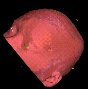
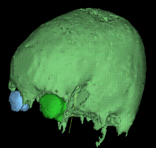
The skull surface is triangulated and a triangle reduction algorithm is
used to reduce the number of triangles. The left and right eyes are
outlined. Shown is the resultant skull and eye surfaces.
The CT series also had a stereotactic frame attached. Because the MRI
series did not have a stereotactic frame, we are going to here match the
skull and eye surfaces to achieve image fusion. We use the
isosurface feature to produce a CT skull. But we do not want to pick up the
stereotactic frame in the surface. To eliminate the stereotactic frame we
first copied the skin surface and added a 0.5 cm margin to it. But we did have
to first edit the skin surface contours to eliminate the points where the
stereotactic frame attached to the patient's skull. Using the body
surface with margin, we generated an isosurface from the image set with a
restriction of the isosurface to inside the body surface with margin.
We needed to add the margin to the body surface as the skull gets close to
the skin in places and we would otherwise have omitted some skull surface.
The skull surface is triangulated and a triangle reduction algorithm is
used to reduce the number of triangles. The left and right eyes are
outlined. Shown is the resultant skull and eye surfaces.
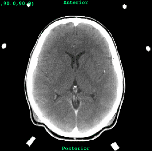
 Next we need a skull surface from the MRI images. To do this we reverse
the contrast of a MRI slice and adjust the contrast so that the skull
appears white as it does on the CT scans. We use an automatic outlining
routine to pick up the skull outline and automatically repeat the process
on all the MRI scans. The contours were also edited to eliminate unwanted
features. Shown is an MRI slice with a skull outline.
Next we need a skull surface from the MRI images. To do this we reverse
the contrast of a MRI slice and adjust the contrast so that the skull
appears white as it does on the CT scans. We use an automatic outlining
routine to pick up the skull outline and automatically repeat the process
on all the MRI scans. The contours were also edited to eliminate unwanted
features. Shown is an MRI slice with a skull outline.
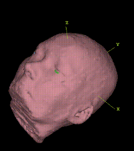
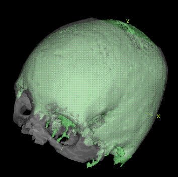
 Shown is the skull surface resulting from the MRI skull contours.
It is important that one of the surfaces to be matched is fairly clean of
unrelated structures. We have used the CT skull in this case. For each
matched surface, one surface, the cleaner and more complete surface,
is designated as the template surface. For the corresponding surface in
the other image series, points from the surface are taken. The distance
from these points to the matching surface is used in a down hill search
method to find the best transformation between two image series.
Shown is the skull surface resulting from the MRI skull contours.
It is important that one of the surfaces to be matched is fairly clean of
unrelated structures. We have used the CT skull in this case. For each
matched surface, one surface, the cleaner and more complete surface,
is designated as the template surface. For the corresponding surface in
the other image series, points from the surface are taken. The distance
from these points to the matching surface is used in a down hill search
method to find the best transformation between two image series.
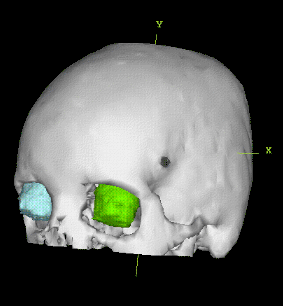
 The two skull surfaces can be viewed together and manipulated manually with
screen controls to the same approximate position. The eye contours make
this manual positioning easier when rotating for two different
orthogonal views.
Then a down hill search
method is used that considers the list of matched surfaces, here matched
skull surfaces and matched eye contours, to find the best correlation
between the two image sets. Shown are the two skull surfaces after the
solution was found. We do note that there appears to be some difference
in the shape of the CT and MRI skulls. We believe that this could be due
to some distortion in the MRI scans and possibly to the different
thickness of skull
that CT and MRI will produce from their respective image data.
The two skull surfaces can be viewed together and manipulated manually with
screen controls to the same approximate position. The eye contours make
this manual positioning easier when rotating for two different
orthogonal views.
Then a down hill search
method is used that considers the list of matched surfaces, here matched
skull surfaces and matched eye contours, to find the best correlation
between the two image sets. Shown are the two skull surfaces after the
solution was found. We do note that there appears to be some difference
in the shape of the CT and MRI skulls. We believe that this could be due
to some distortion in the MRI scans and possibly to the different
thickness of skull
that CT and MRI will produce from their respective image data.
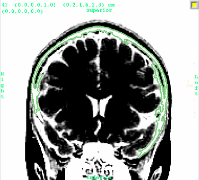
From the image fusion solution we can then reformat a plane from the CT scan image set in the MRI series for the same corresponding plane, shown below with the CT scan on the left, the reformatted MRI scan on the right.
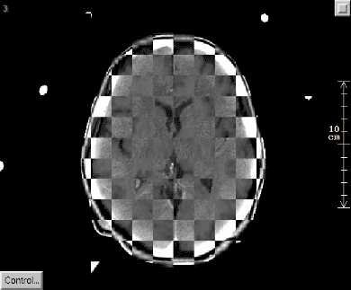 Next we overlay these two images on top of each other in a checkerboard
pattern, so that every other square shows the same image data, with adjacent
squares alternating showing CT and MRI data from the two images.
Next we overlay these two images on top of each other in a checkerboard
pattern, so that every other square shows the same image data, with adjacent
squares alternating showing CT and MRI data from the two images.
Return to Prior Page
Return to Home Page
Math Resolutions, LLC