
|
www.MathResolutions.com
Software Products for the Radiological Sciences
| Search |
|
www.MathResolutions.comSoftware Products for the Radiological Sciences |
|
| Home Page | Product Review | Program Manuals | Download Programs | Purchase | Site Map |
| Dosimetry Check | MarkRT (VGRT) | RtDosePlan | System 2100 | MillComp | C++ Library |
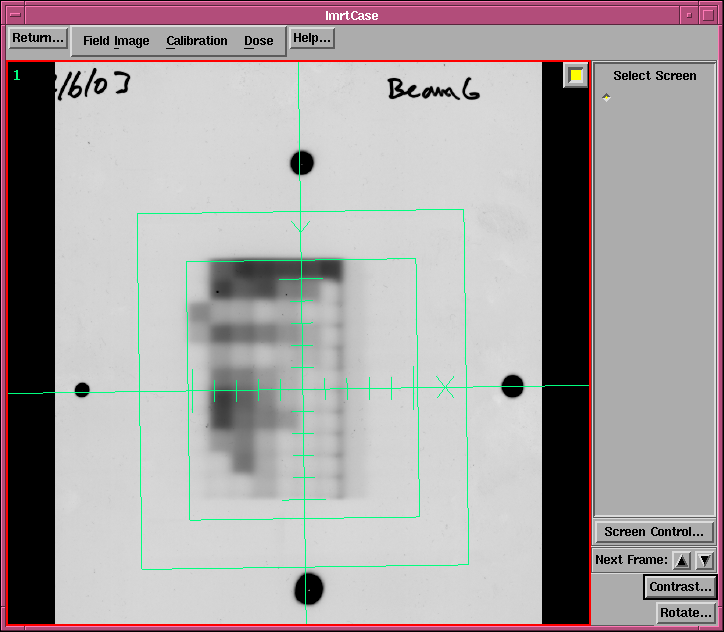
Use the Screen Control button at the lower right hand corner to create a screen of empty frames. The frame locations are filled with big buttons. Hit a botton to select a frame. Then under the Field Image pulldown, select an image file to read. The formats include tif, png, Dicom, and RIT.
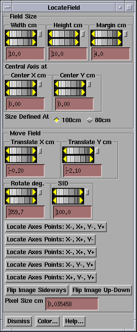
Again under the Field Image pulldown, select Locate Field. First use the Translate X and Translate Y under Move Field to center the cross hairs using pin marks in this case. There is also a rotate control. Use this method if there are any visual alignment marks.
ORyou can use the mouse to click on the the pin marks. By hitting the Locate Axes Points X-, X+, Y-, Y+, the program expects you to click on points in the order of: a point on the X axis, then a point on the X axis that is more positive, then a point on the Y axis, then a point that is more positive on the Y axis. The program will then solve for the transformation. Use the other buttons for any combination of only three alignment marks on the film.
Once that is done, use the width and height control to define the rectangular outline of the field. This information is used to draw a border in beam's eye views. Then use the margin contol to include as much area around the field as possible up to at least 2 cm.
It is what is inside the margin that is used. The width and height are used for informational purposes only. It is important that the central axis be accurately located and the beam's eye view axis directions are correct. The beam's eye view x and y axis rotates with the collimator. You define what the nominal collimator angle at which the beam's eye view axis are relative to in a file in the accelerator directory called Geometry. At the nominal collimator angle, with the accelerator pointing at the floor, the X axis goes across the couch from left to right while looking into the gantry, the Y axis is parallel to the gantry's axis of rotation, pointing toward the gantry.
Note the source image distance control (SID) for defining the distance the image is taken at. This must be accurately set. You can define the default distance to the image holer in a file in the accelerator's beam data directory called ImageHolders (see the Field Dose section in the manual).
The Center Axis controls are for the case of asymmetric fields. If using them you would normally locate the field and move the axis to the central ray. This feature is here to help locate fields for more conventional cases.
Return to Quick Start Page